Following up on our first post, Vision and overview of the utility network, we wanted to give you an opportunity to ‘get under the hood’ of the utility network by discussing the foundational components of domain and structure networks. The ArcGIS Utility Network allows you to model how all components of the utility system are related, intelligently handle dense collections of features, and perform complex tracing analysis within the network. These capabilities are delivered through ArcGIS Pro and ArcGIS Enterprise with the ArcGIS Utility Network.
The utility network data model is designed to be highly scalable by limiting the number of base feature classes and incorporating a rich classification system that is built into the schema of each feature class. All of the base feature classes for the utility include two attributes (ASSETGROUP and ASSETTYPE) that incorporate the use of subtypes and attribute domains assigned at the asset group level. The ASSETGROUP field is used for major classification, while the ASSETTYPE field is used for minor classification of network features. To learn more, see Utility feature classification.
Let’s jump right in and discuss the concept of domain and structure networks and explore these foundational pieces of the utility network.
Domain networks
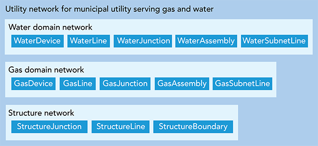
First, let’s discuss the concept of domain networks. It is common for a municipality to manage one or more types of commodity networks. In the utility network, domain networks are equivalent to commodities. A deployed utility network can contain one or more domain networks and one structure network. The number of domain networks maintained is determined by the type of model you are building and the industry you manage.

How are domain networks created? When you configure your utility network, domains are created using the Add Domain Network tool or as part of the automated process for configuring a utility network via the Utility Network Package Tools. Domain networks can be added to an established utility network if business needs change over time. For example, an additional domain network can easily be added to an existing utility network if a municipality that manages a water domain expands to add a gas domain.

The real world has many interdependencies between different utilities. The utility network enables the real-world model to come to life by allowing capabilities such as connectivity between features from different domain networks. For example, you can have an electric domain network that feeds a water pump. Gas pipeline networks can be utilized to illustrate the network that supports electric combined cycle generation.
Tiers
Utility systems are often organized into operational groups for the delivery of a utility resource. An electric system is organized into transmission (high voltages), distribution (medium voltages) and secondary (low voltages). Gas and water systems have tiers for the gathering of gas or water, transmission of gas or water over long distances, and distribution of gas or water to the consumer. Domain networks within the utility network can be divided into tiers to segregate and manage subnetworks. Tiers model the hierarchy of how the network delivers resources such as gas, electricity, and water and can represent ranges of pressure, voltage or other characteristics of the network.
An electric distribution system can be divided into multiple tiers of sub-transmission, medium voltage, and low voltage levels. Tiers can also represent parts of the network that can be isolated from one another such as a valve isolation zone in a pressure-based system. They all have unique rules and templates for responsive and appropriate integration. With the utility network, those rich rules and procedures can remain in place while your distribution and transmission features can communicate or trace across domains, providing solutions that best fit the business and end-user.
The tier definition chosen for the domain network controls the organization of tiers relative to the rest of tiers in a domain network and also decides the permissible tier topology types. You will have either a collection of partitioned successive tiers or a hierarchy of nested tiers. Tiers reside at either the domain network or at the tier group level, depending on the type of model you are working with. There are two ways of organizing a domain network, using a partitioned or hierarchical tier definition.
- Partitioned tier definition – Partitioned networks support systems that are sequential in nature, such as electrical and telecommunication utilities. Partitioned domain networks support both mesh and radial tier topology types for subnetworks. In partition systems, tiers reside inside of a domain network.
- Hierarchical tier definition – Hierarchical networks allow you to model networks that are nested, such as gas and water networks. Hierarchical domain networks only support mesh tier topology type for subnetworks. Hierarchical domain networks require tiers to be contained within tier groups.
Tiers can further contain a collection of subnetworks. Subnetworks are a subset of a tier that represent a collection of features connected to the same subnetwork controller. Flow or load-based controllers can be used to create subnetworks or circuits across domains. For electric utilities, this could be a circuit breaker or transformers to identify customers associated with distribution circuits and opportunities for fault isolation and sectionalizing. Gas networks could use pressure valves or regulator stations to determine safe operating conditions for all the downstream assets within the subnetwork. Finally, with containment assemblies, detailed switch and phasing elements can be modeled in real space and efficiently projected in the context of the map framework. All this means a better foundation for practical analysis and modeling across your utility, with opportunity for integration with Esri partner solutions for inspections, surveys, environmental, forestry and other operational needs.
Structure network
When discussing domain networks it is hard not to talk about structure networks. The structure network is shared amongst all domain network features within the utility network. Features within the structure network do not have any resources such as water or electricity flowing through them but serve to support other network features that are part of delivering a commodity. For example, a vault (which is a structure) can contain valves and regulators that are features of a domain network.
The structure network promotes non-networked features into network awareness. It allows you to expand the foundation model into a wide range of informative products such as inspections, or business intelligence deliverables about all aspects of the utility business. Items like poles, pads, ducts, trenches, stations, and casings are now network aware and can be projected in 3-D space because of its z-scale awareness.
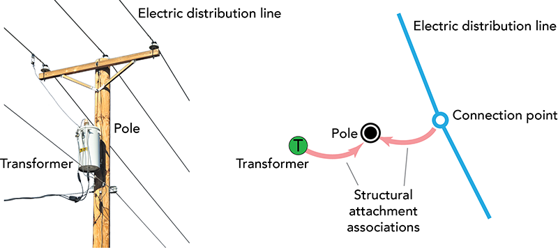
The key purpose of a structure network is to support a type of association called structural attachments. This is a way to efficiently identify which domain network devices or lines are attached to a structure feature. This satisfies a utility’s need to rapidly identify which structure, such as a pole, is associated with a device that may be experiencing an outage. Structural attachments can also be used to create a list of structures that are supporting a section or utility subnetwork. In another post, we will dive deeper into the concept of structural attachment associations.

In conclusion, because the utility network can operate across electric, gas, water and fiber domains, companies and municipalities are no longer required to silo their data. Instead, users can experience the impact of energy flow models to locate regions for proper development, predict future load requirements, and even model fuel sources such as supply-side gas pipelines for electric generation facilities. These expanded workflows let operation centers provide a clearinghouse of all spatial information and build information solutions to support effective business decision making.
– Remi Myers, Esri Utility Network Product Manager
This post was originally published on February 5, 2018, and has been updated.


Commenting is not enabled for this article.