Introduction
Update: ArcGIS Pro 3.5 added new tools to bulk apply error resolutions to topology errors. The concepts outlined in this series of articles are important to understand when choosing which actions to use when resolving your errors. Learn more about how to use these new tools by reading the Analyzing topology errors and Resolving topology errors articles.
Many gas organizations have recently implemented or are about to implement the Utility Network for Gas. For the editors in these organizations, this new capability will also include a new set of capabilities to help enter the data correctly. A key tool in helping editors of your pipe network to correctly enter data is the Validate Network Topology tool. The first time you run the Validate tool on your utility network and encounter a topology error, you will likely ask yourself three questions:
- What caused this error?
- How can I fix this error?
- What can I do to prevent this from happening again?
The purpose of this article is to provide gas industry-specific examples of the most common errors, so you are better equipped to answer these three questions. The different resolutions aren’t always immediately obvious, and we hope this guide will help you quickly identify the solution that’s the best choice for your data and your specific situation. If you’re not already familiar with error management in the utility network, you will want to familiarize yourself with the following resources:
- You can find a full list of all the possible network errors on the Errors topic in the online help.
- Read the Feature restrictions and rules topic to learn the difference between a network rule and a feature restriction, along with the constraints for what types of features can be connected or associated.
- Read the Dirty area management with the utility network article to learn how the utility network uses dirty areas to track and validate edits made to the network topology.
- Read the Managing Topology Errors article for a higher-level overview of error management.
You can find more gas and pipeline utility network related content in the Learn ArcGIS Utility Network for Gas and Pipeline learn series, including these hands-on tutorials related to this article:
- Fix Connectivity Errors in a Utility Network
- Fix Topology Errors in a Utility Network
- Configure rules for a Utility Network
This article covers the following types of errors:
| Error Type | Error Description |
| Junction-Edge Errors | 8: Invalid connectivity – No junction edge rule |
| Ambiguous Connectivity | 9: Invalid connectivity – More than one junction edge rule applicable |
| Edge-Edge Errors | 10: Invalid connectivity – The edges are different subtypes and cannot connect |
| Stacked Points | 25: Stacked point features |
| Invalid Terminal Connections | 36: The line feature has an invalid terminal |
| Midspan Terminal Devices | 38: Devices with multiple terminals cannot be midspan |
Junction-Edge Errors
Fix Incorrect data
The Utility and Pipeline Data Model (UPDM) is the industry data model for the natural gas and pipeline industries. One of the quality control configurations of the utility network rulebase included in this data model is to prevent editors from incorrectly connecting plastic assets to metallic assets. Not defining the material type for a fitting, device, or pipe segment will prevent it from being able to successfully connect to another fitting, device, or pipe segment because features without materials don’t have any connectivity rules.
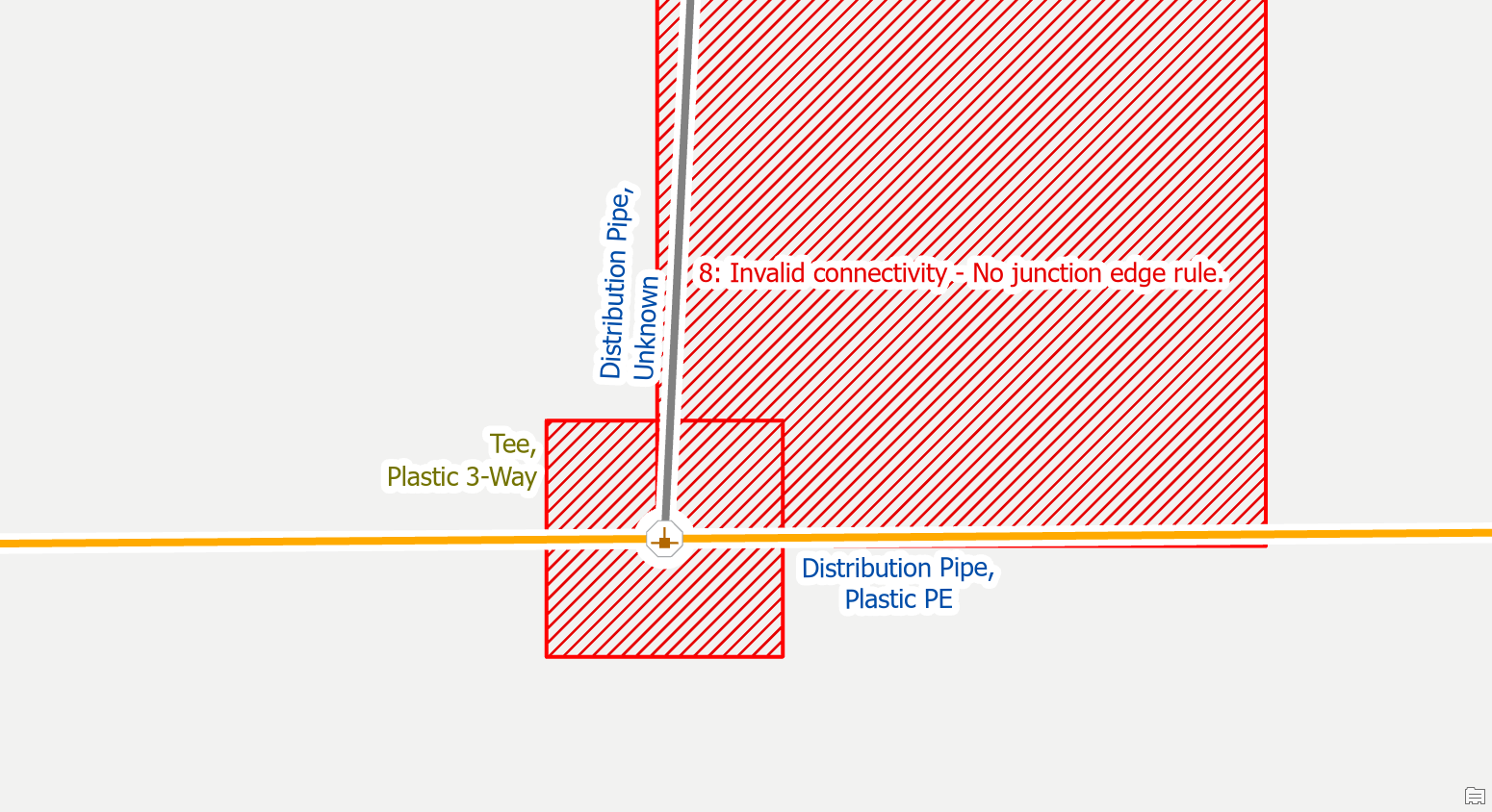
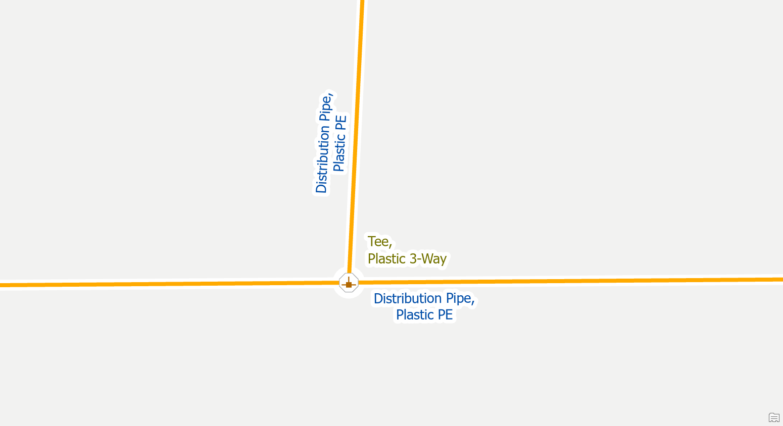
To resolve the issue, you need to correctly classify the pipe or device with an unknown asset type.
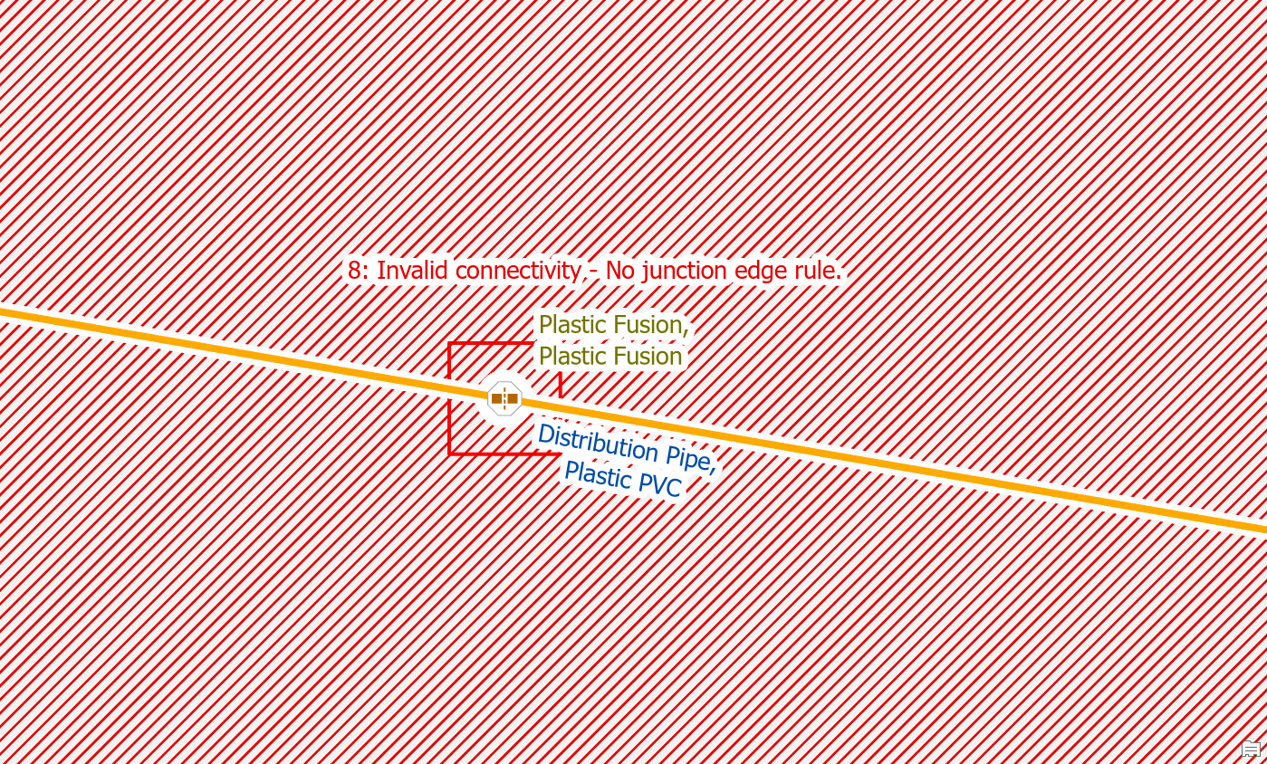
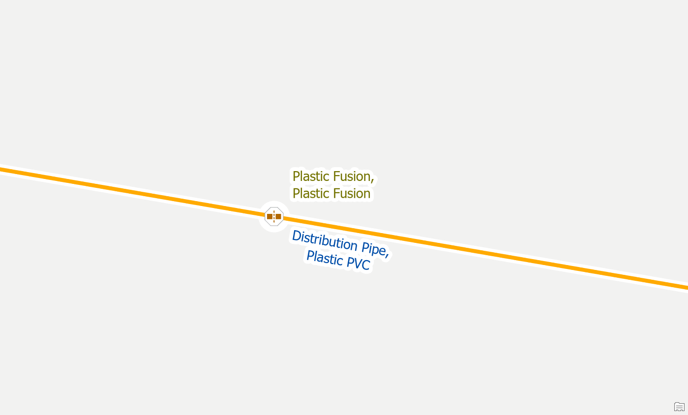
Add a rule
You must add rules to your network for any feature you wish to include in your data. If you place a feature in the map that doesn’t have any rules, or the feature is being used with a combination of materials that there aren’t rules for, you will receive errors on it and will be unable to update the corresponding subnetwork.
To fix the error an administrator would need to disable the network and add the rule(s) required for the new type of feature to allow it to connect to different lines, junctions, devices. They will also need to add the new type to the subnetwork definitions for the system and pressure tiers.
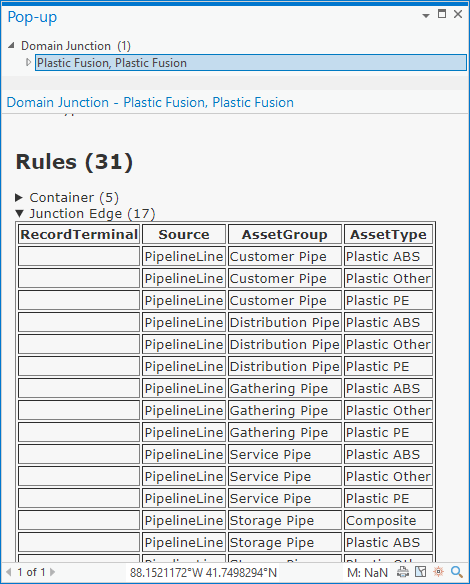
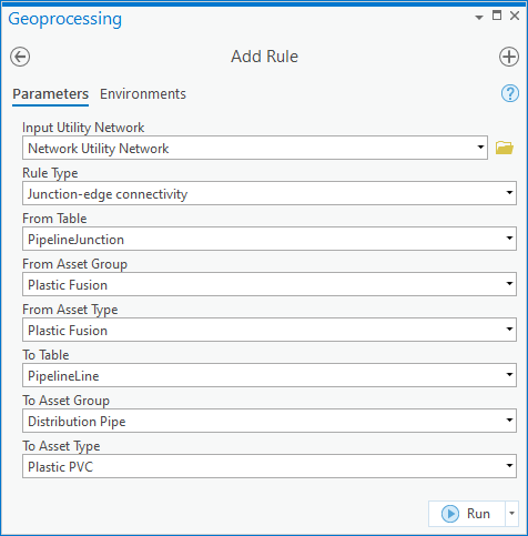
Once the rule(s) have been added and the network has been re-enabled the error(s) will be resolved.
Ambiguous Connectivity
Use Terminal Connections tool
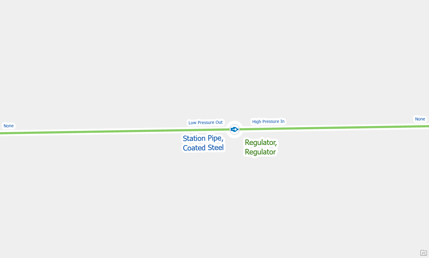
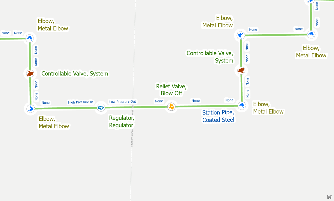
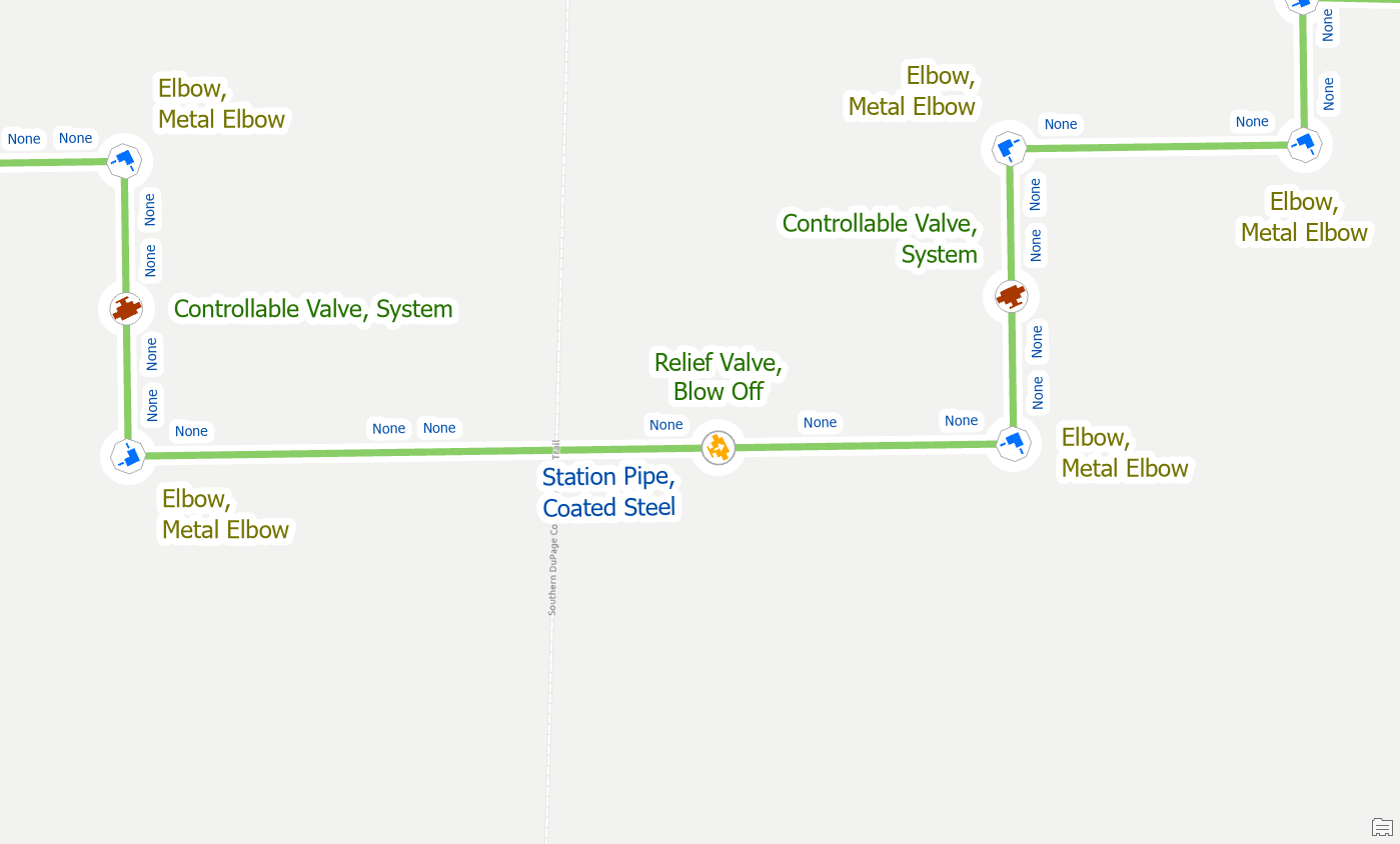
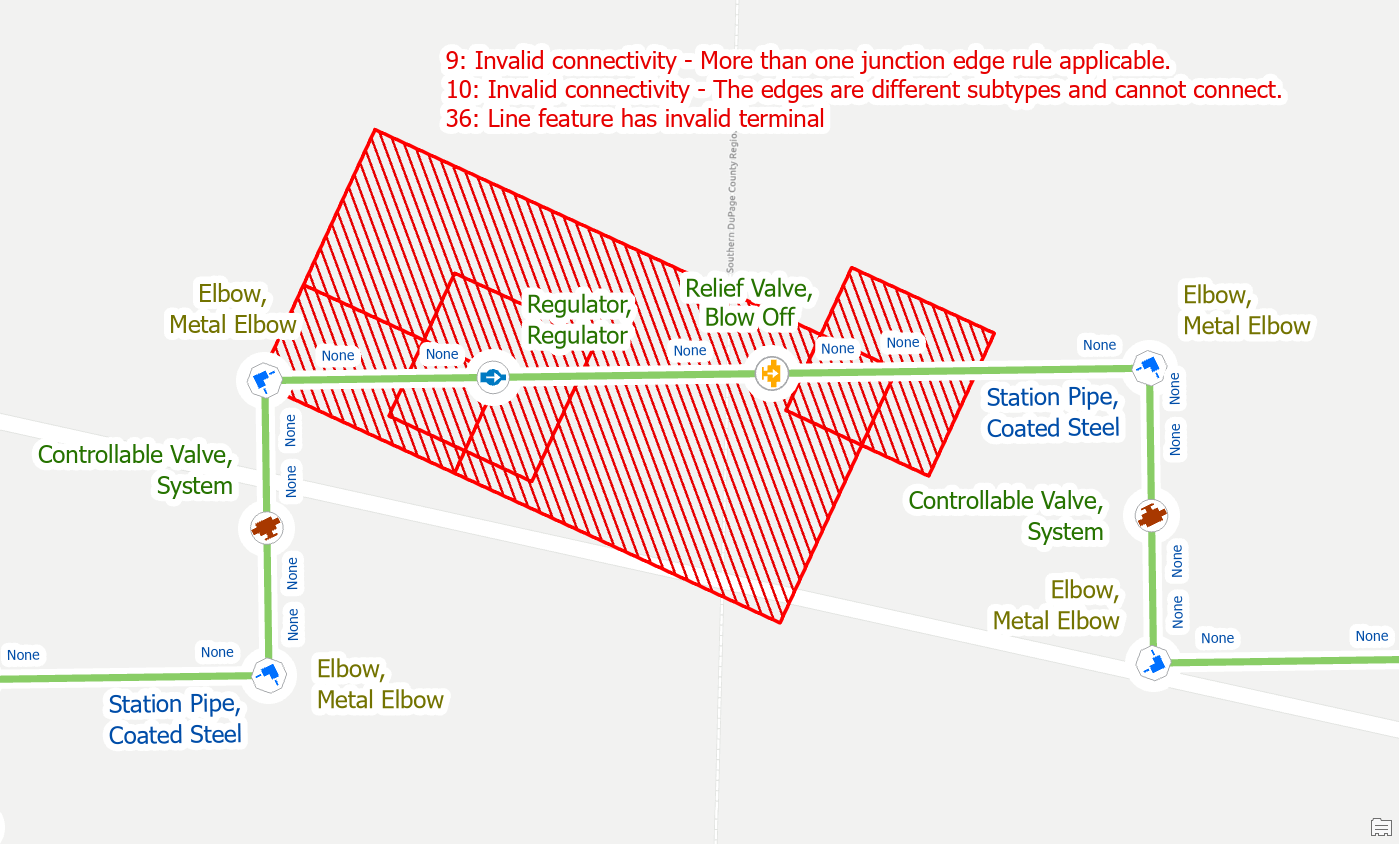
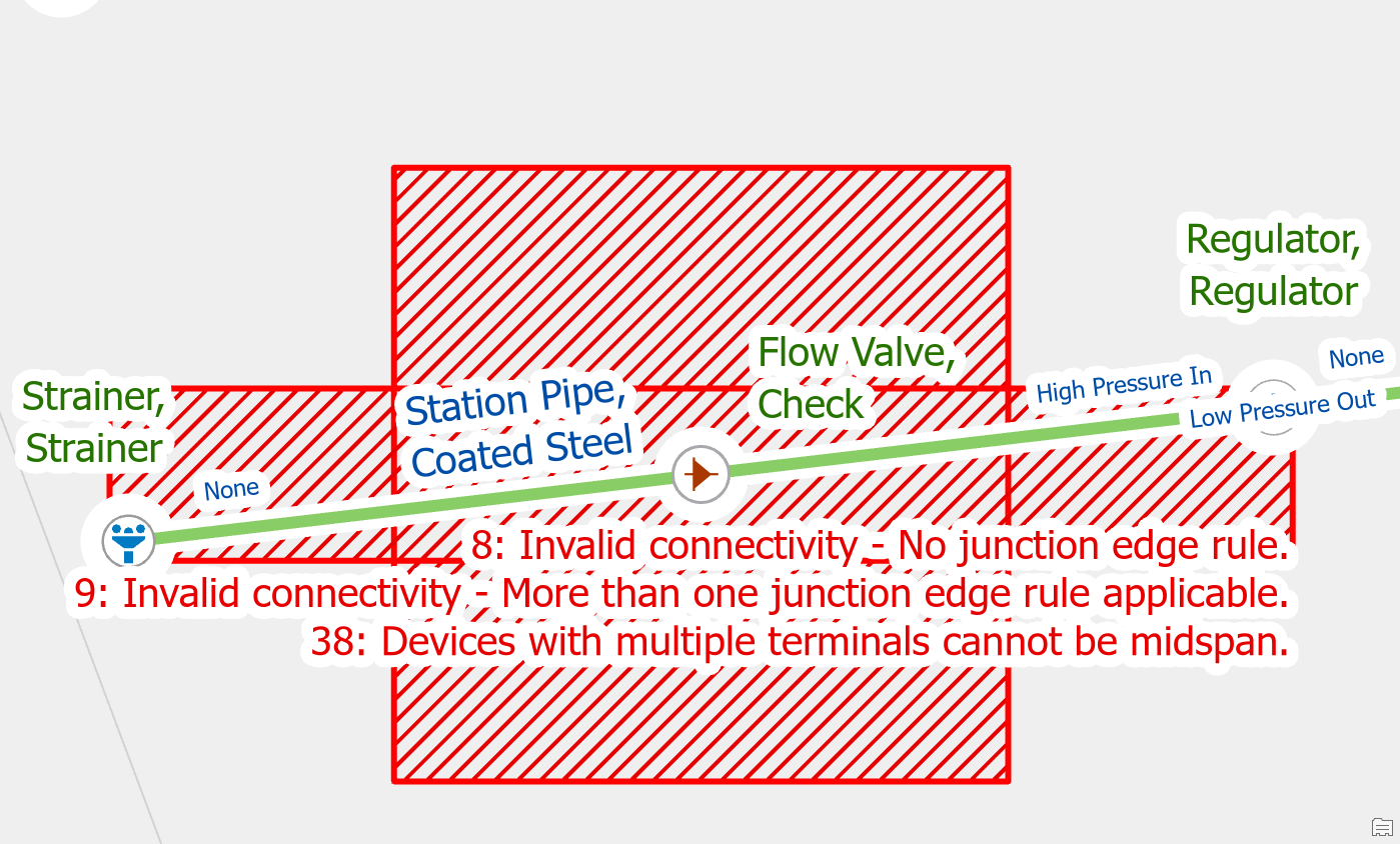
If you forgot to assign the terminal connections on the lines after creating a regulator you will run into this error. A regulator is the source device to pressure zones and must be defined as a subnetwork controller. Part of defining the regulator as the source to a pressure zone requires the defining of which pipes are providing gas to/from the regulator.
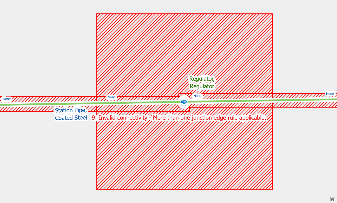
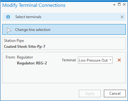
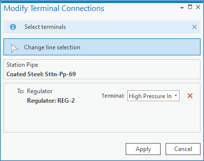
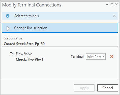
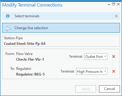
To correct the error, you can use the assign terminals tool on each line that connects to the regulator to assign the line to the high-pressure inlet / low-pressure outlet of the regulator.

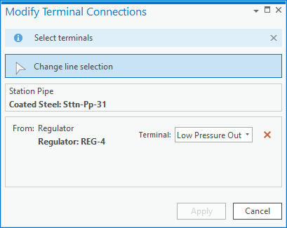
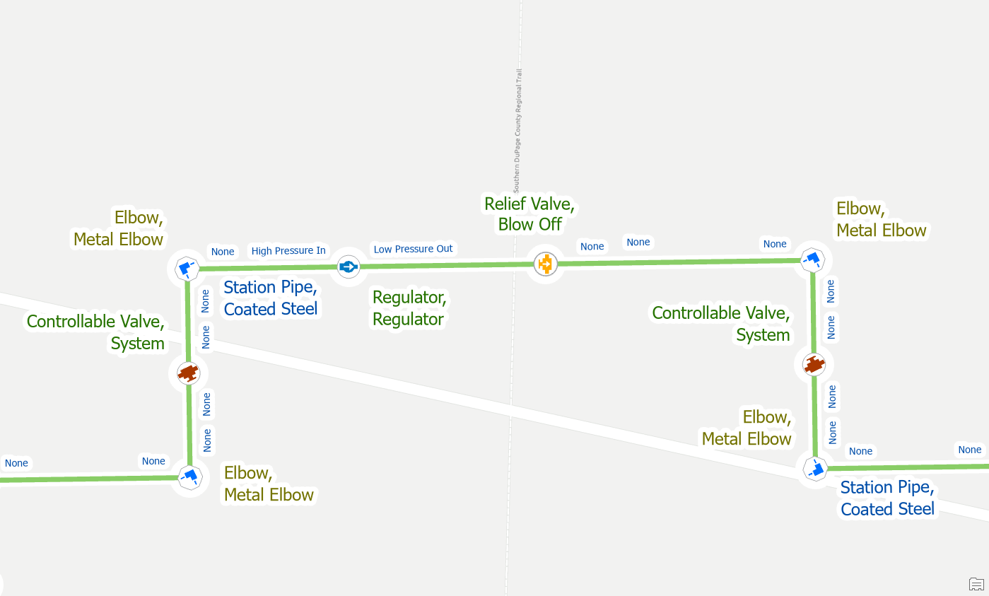
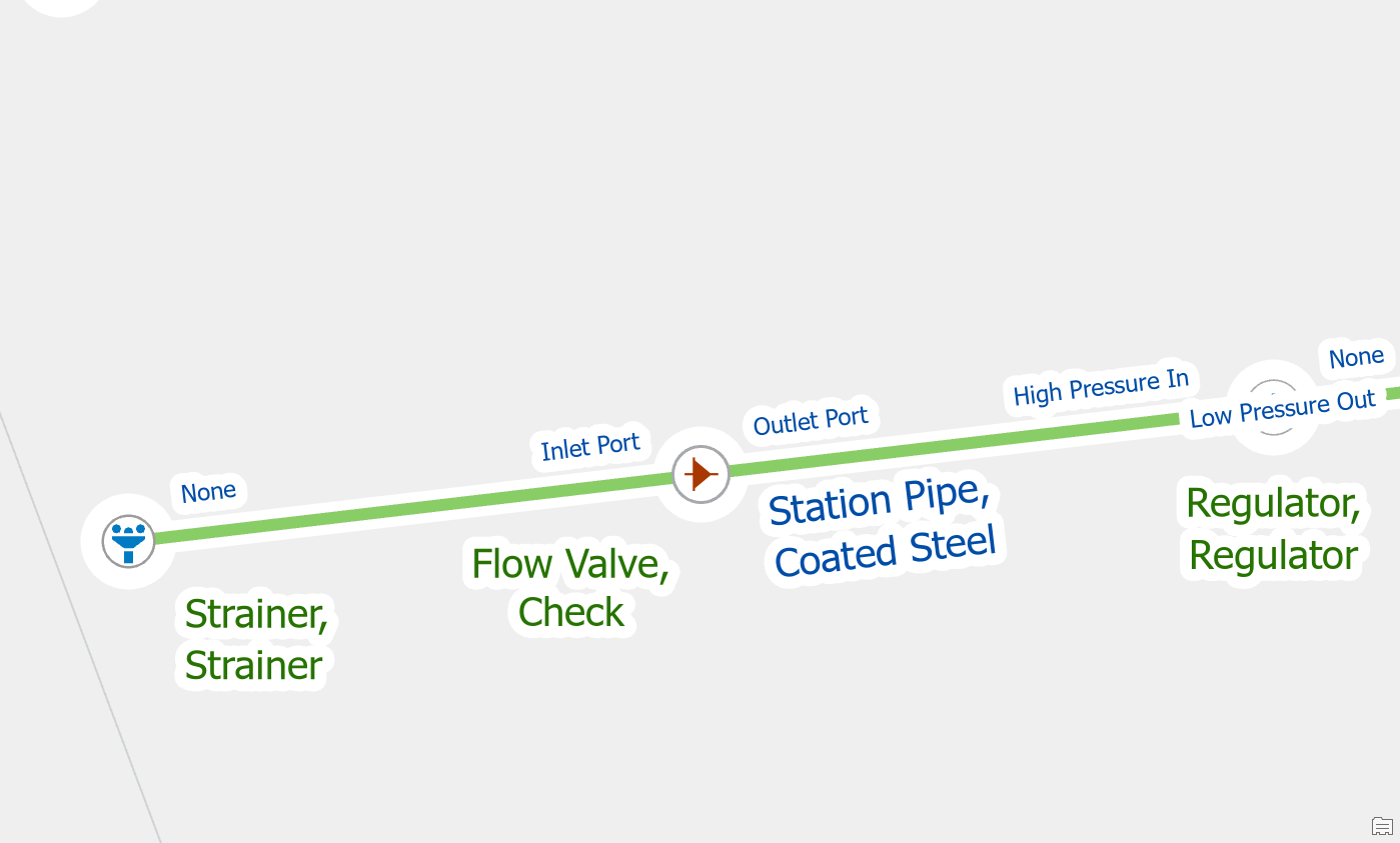
Once you’ve connected the lines to the terminal and validate your edits the errors will be gone.
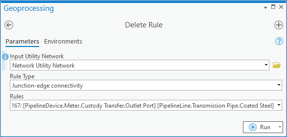
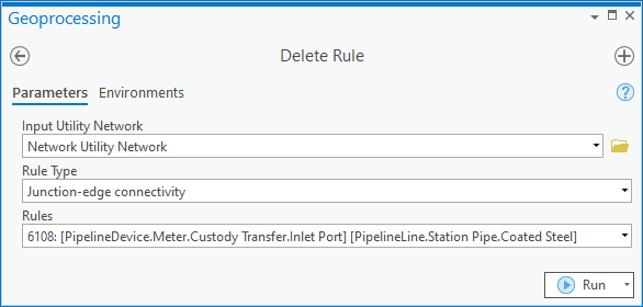
Remove the invalid rule
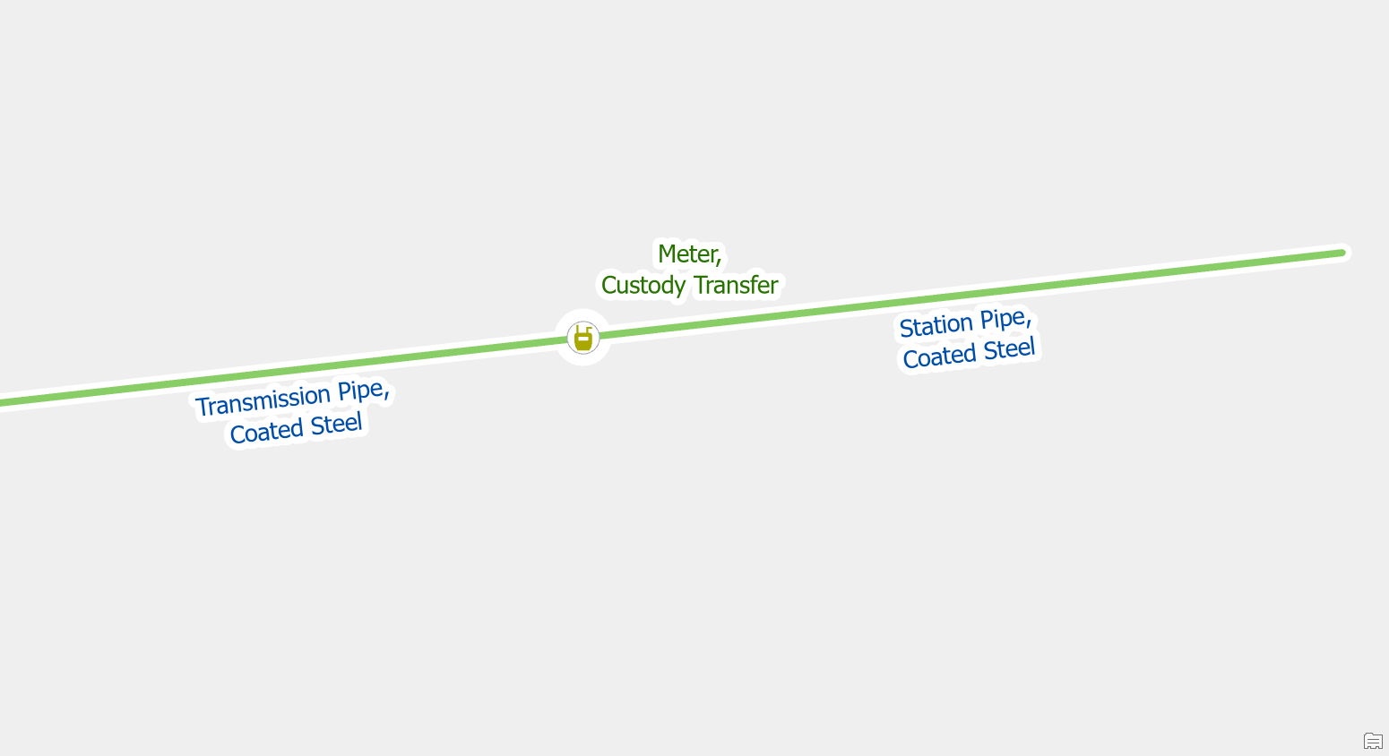
By default, the gas model allows transmission pipe and station pipe to be on both the inlet port and outlet port of a custody transfer meter.
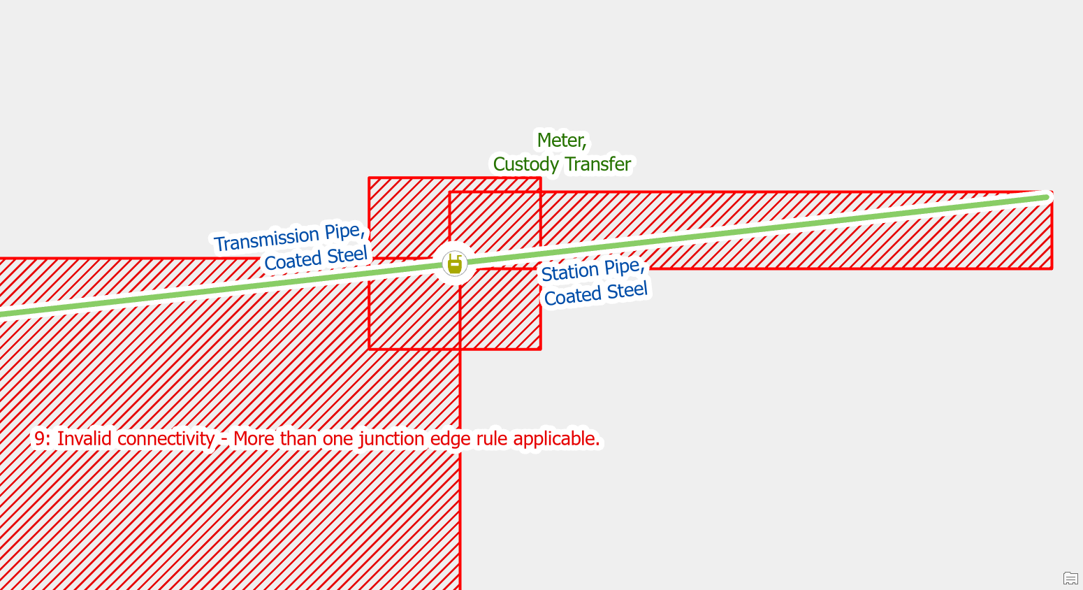
This means you must use the terminal connection tool when connecting a main to a regulator to assign it to the right terminal. We can confirm this by reviewing the rules assigned to the custody transfer meter.
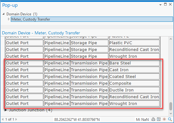
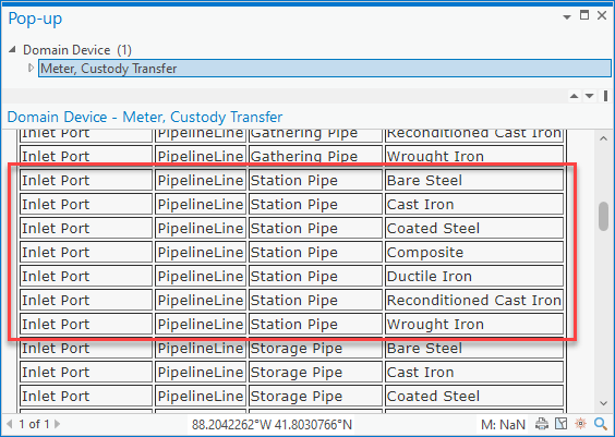
If your data only allows for transmission to be on the inlet and station on the outlet, then you can adjust your rules to reflect this. This will ensure that these pipes can only connect to the correct terminal.
Once you’ve re-enabled your topology you will find that these pipes will automatically connect to the correct terminal of the custody transfer meter, meaning you don’t have to use the terminal connection tool.
Move one of the features
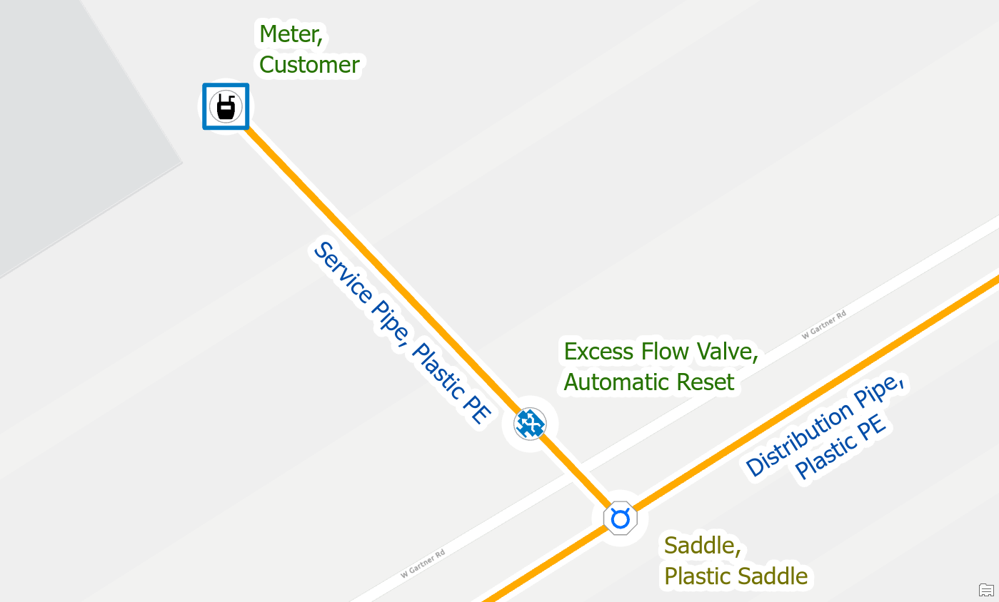
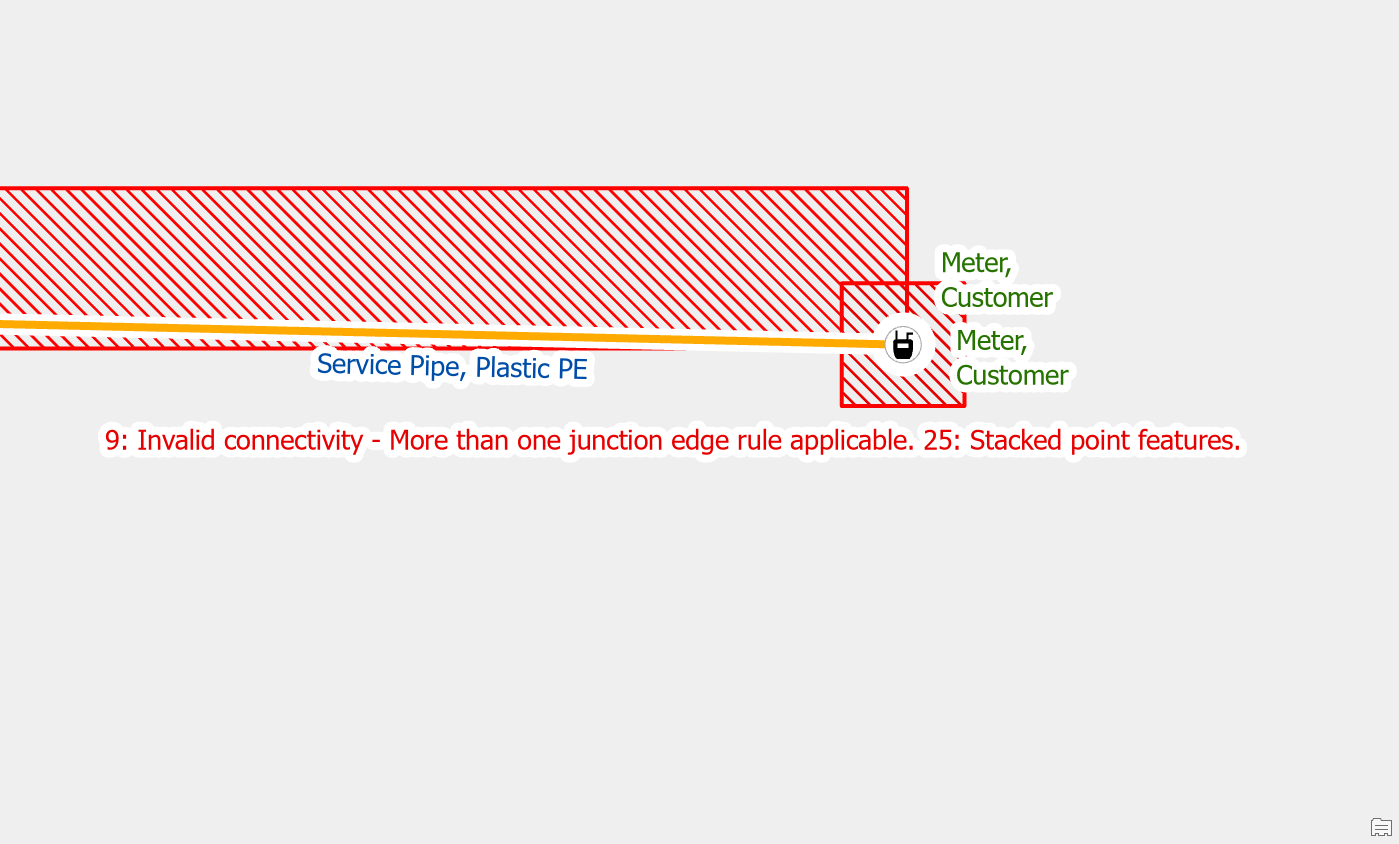
If you have an excess flow valve drawn on top of a saddle or other fitting at your service connection, you will see several errors:
- Ambiguous connectivity error because the junctions and lines each have multiple rules
- Stacked point feature errors for the junction and device.
- Edge-Edge errors for the underlying lines because none of the junctions or devices at the area have connected the edges
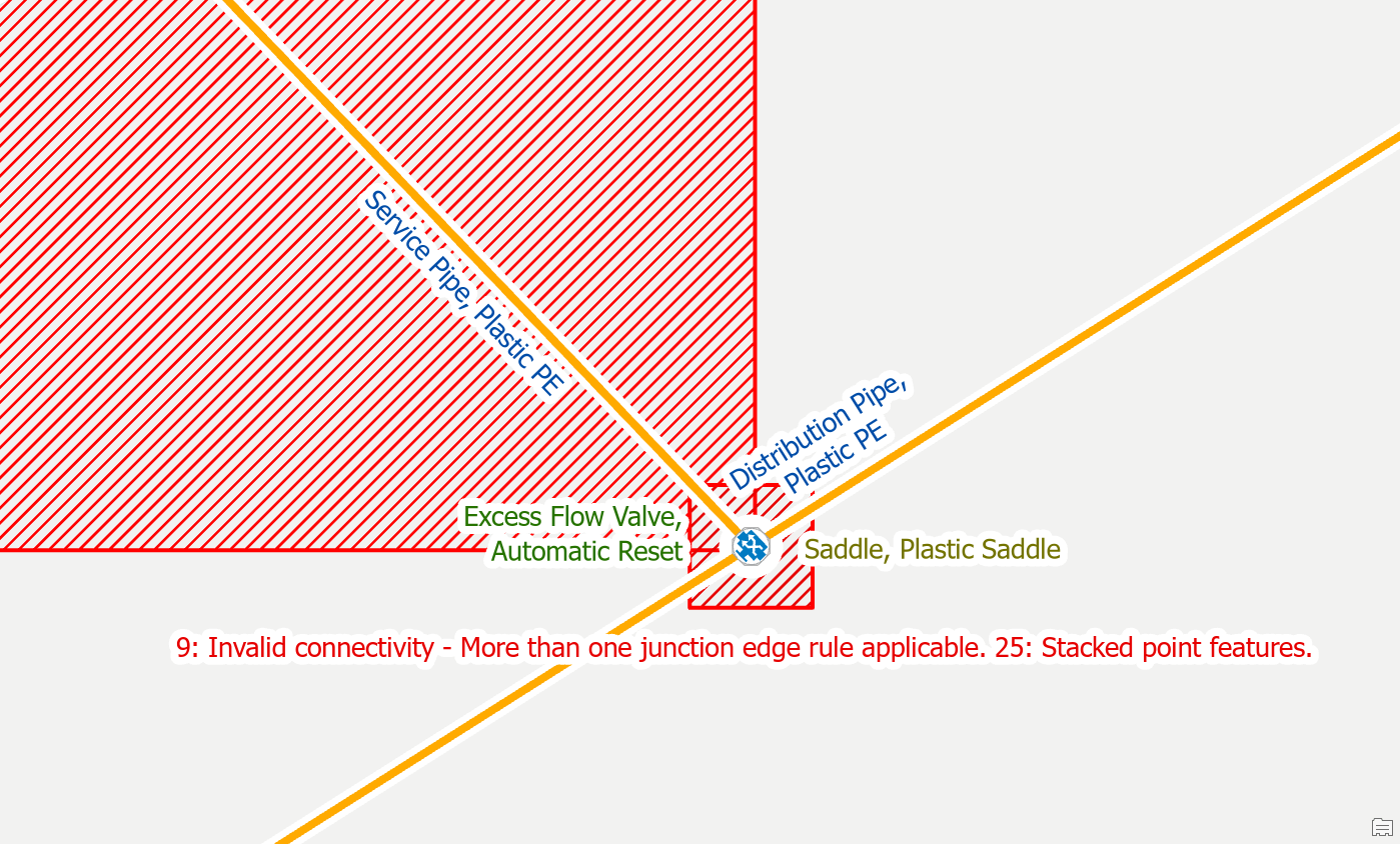
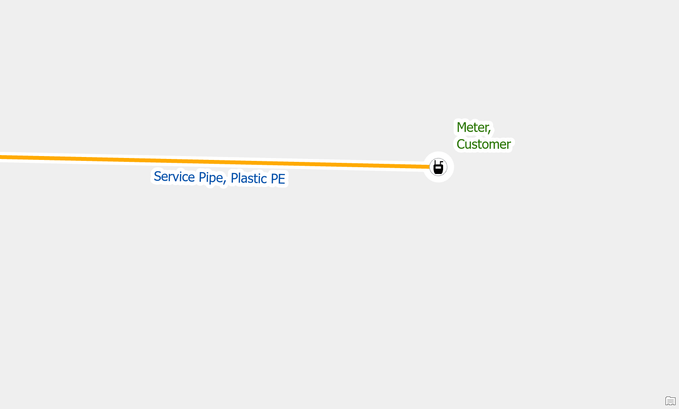
In the field we know that these two features are very unlikely to be physically stacked on top of each other. They are most likely within 12 inches of each other, but horizontally spaced apart. To resolve these errors, you can offset the excess flow valve by moving it away from the saddle, along the service line. By unstacking the junction and device you will clear all the errors associated with that location.
Edge-Edge Errors
Create a point feature
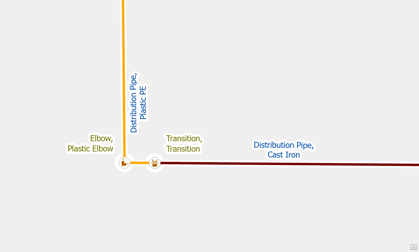
Another common cause of this error is when two different pipes really are connected but you have not modelled the fitting or device that connects them. The most common examples of this are when services connect directly to a distribution pipe or when a user forgets to place a transition on a pipe.
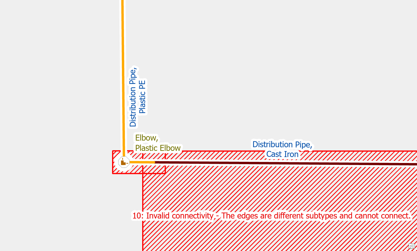
To resolve the issue, you would place a fitting at the location where the two pipes connect. You should make a note or indicator to keep track of these junctions for follow-up. You will need to confirm their location and material later by referring to source drawings, work orders, or field verification.
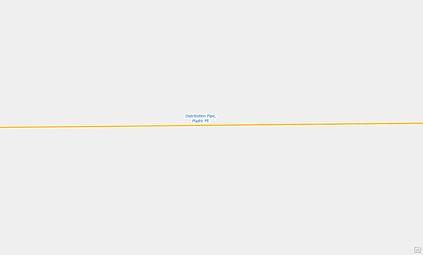
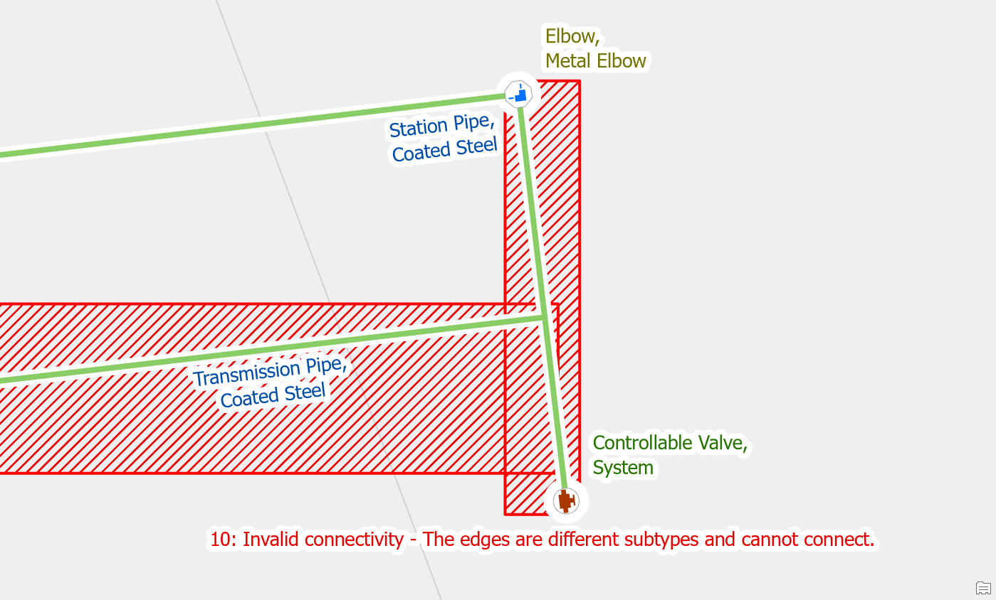
Edit the line features to match
In the gas data model, the assetgroup defines the type of pipe or wire, such as service pipe, distribution pipe, and station pipe. The assettype defines the generic type of material of the pipe, such as coated steel, and plastic PE. When connecting two pipe segments, the unique combination of assetgroup and assettype must match for automatic connection. If the two pipe segments are different, this will generate an edge-to-edge rule error.
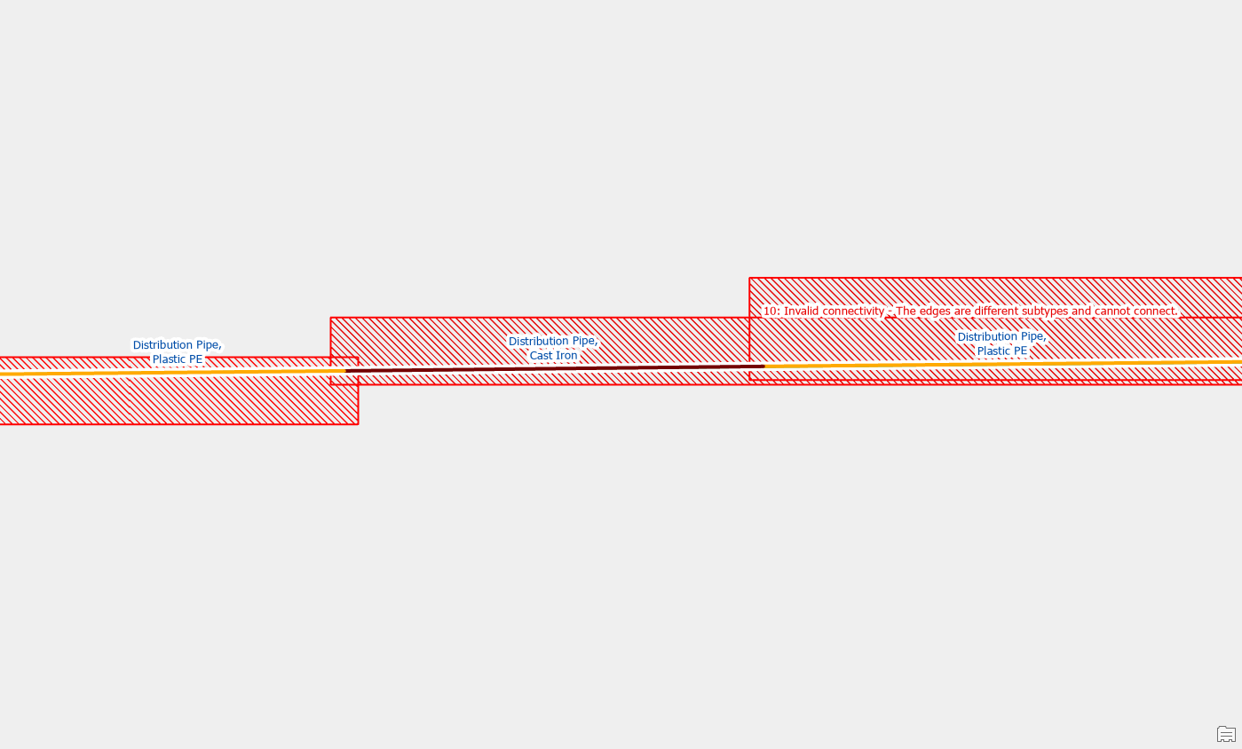
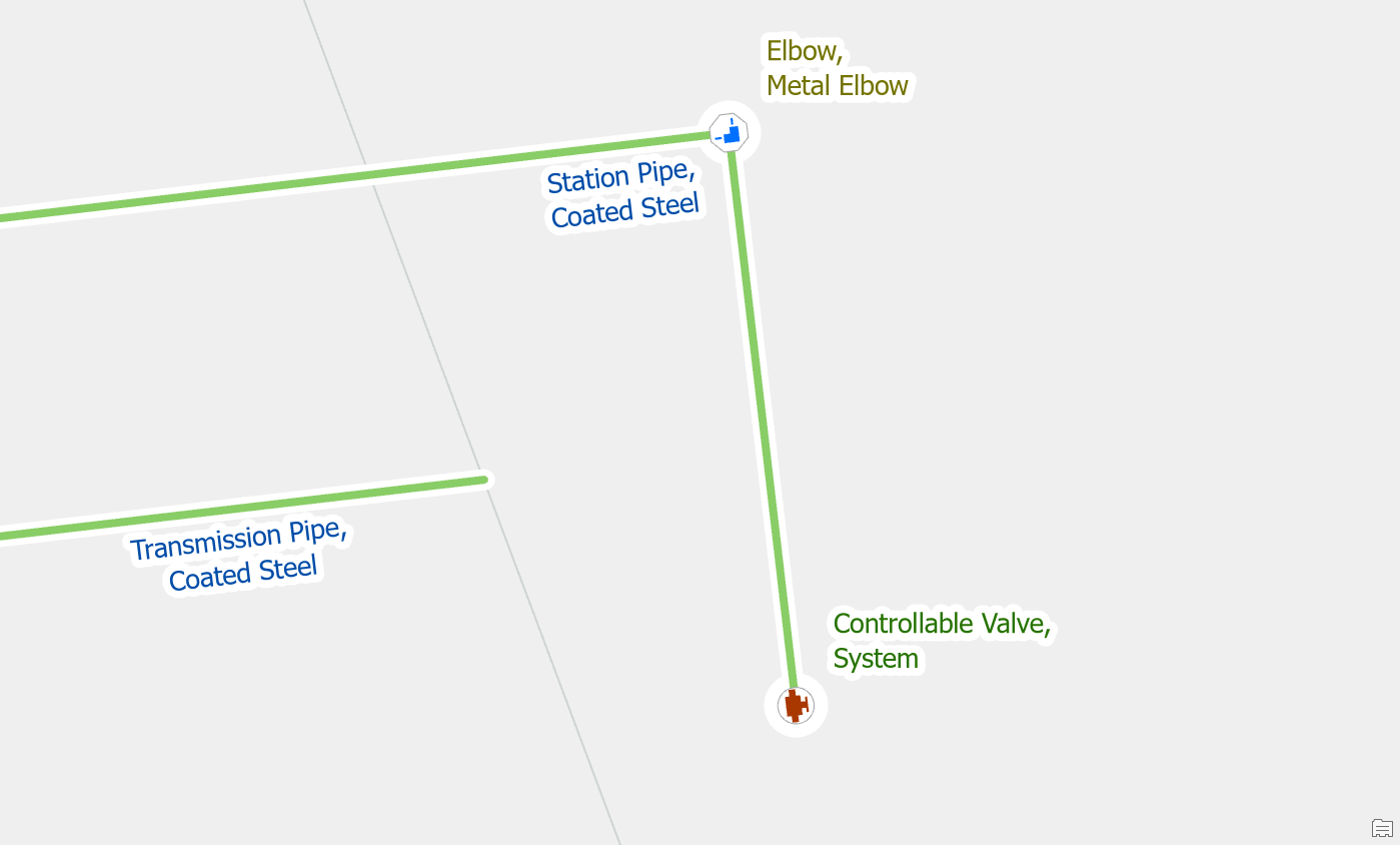
If the situation appears to be caused by a pipe that was incorrectly split and or classified, you can edit the line feature to correct the error. If you think the problem is how the line is classified, you should just update the material of the line. If you think the error is caused by a line that was inadvertently split, you can use the merge tool to combine the two (or more) lines into a single line segment.
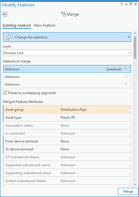
Once you’ve merged the lines and validate the area the errors will be resolved.
Move a line
The Utility Network prevents you from snapping different pipes together in a way that causes this error. This error most often occurs when improperly snapped data is imported from outside of the GIS. If the previous resolutions did not apply to the issues, then you will need to disconnect the two lines using the following steps:
- Select the pipe that needs to be unsnapped
- Activate the edit vertices tool
- Activate the disconnect option
- Move the vertex of the first line away from the second
This will cause the error to go away, but if this results in the feature becoming isolated from your network you will need to research how it is connected.
Stacked Points
Delete one of the stacked features
When you import customer meter locations into the GIS for the first time, it is common for meters to be stacked on top of each other. In the example below we have two meters stacked on the end of a single service.
To resolve the issue, we first confirm that there is only one meter at this location and that the second meter is a duplicate. Once we’ve confirmed that we delete the duplicate meter.
Move one of the features
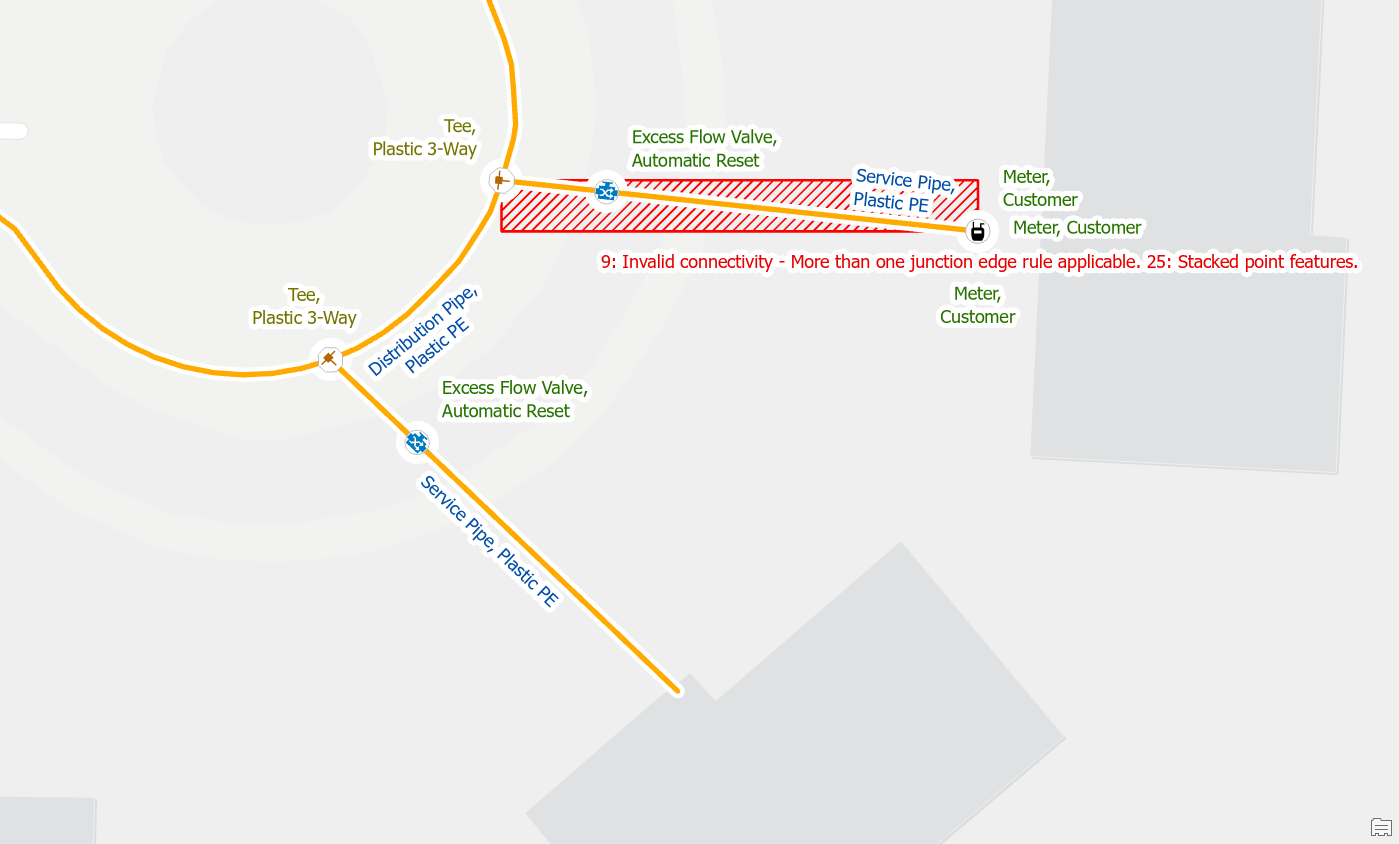
Let’s consider another situation during our cleaning up data after importing customer meter locations. In this situation we are cleaning up data at an address that has multiple meters, caused by a larger parcel being subdivided into several smaller parcels. We investigate the stacked meters and have determined that all of them are active and are just placed in the wrong location.
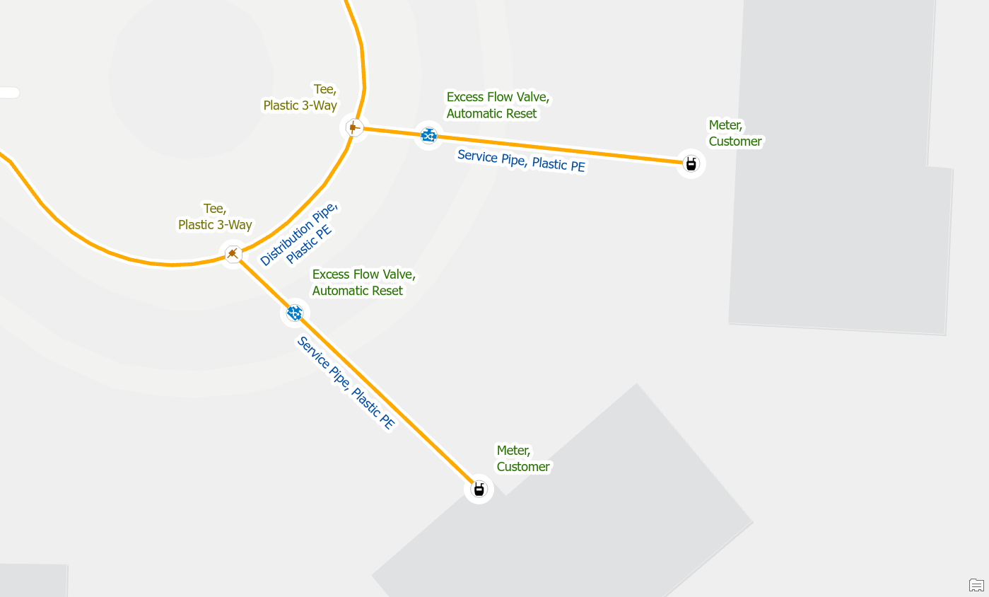
In this situation you would unstack the meters and connect each one to its own service line. If your data does not have enough service lines, or if it is unclear which meter is associated with each service line, then you may need to perform a field check to find the true location of each meter.
Invalid Terminal Connections
Reset terminal connection
If you delete or move a device with terminals from a line, the line will still have attributes that reference the terminal from the previous line. In the example below we are trying to update a station and have discovered that there should not be a regulator on this pipe.
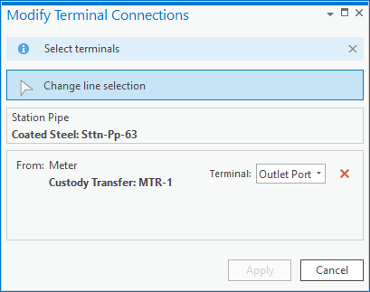
After deleting the regulator, we get errors on the pipes it was connected to saying we’re connected to an invalid terminal. The recommended way to fix the error is to use the Modify Terminal Connections pane to correct the issue. Delete the invalid connection and click Apply.

Once you’ve removed the terminals validated the area you will see the errors have been resolved.
Connect new terminal
You will also encounter this error sometimes when moving a device with terminals or replacing a device with a different terminal configuration. In this example below we have found that the regulator has been drawn in the incorrect location within our station.
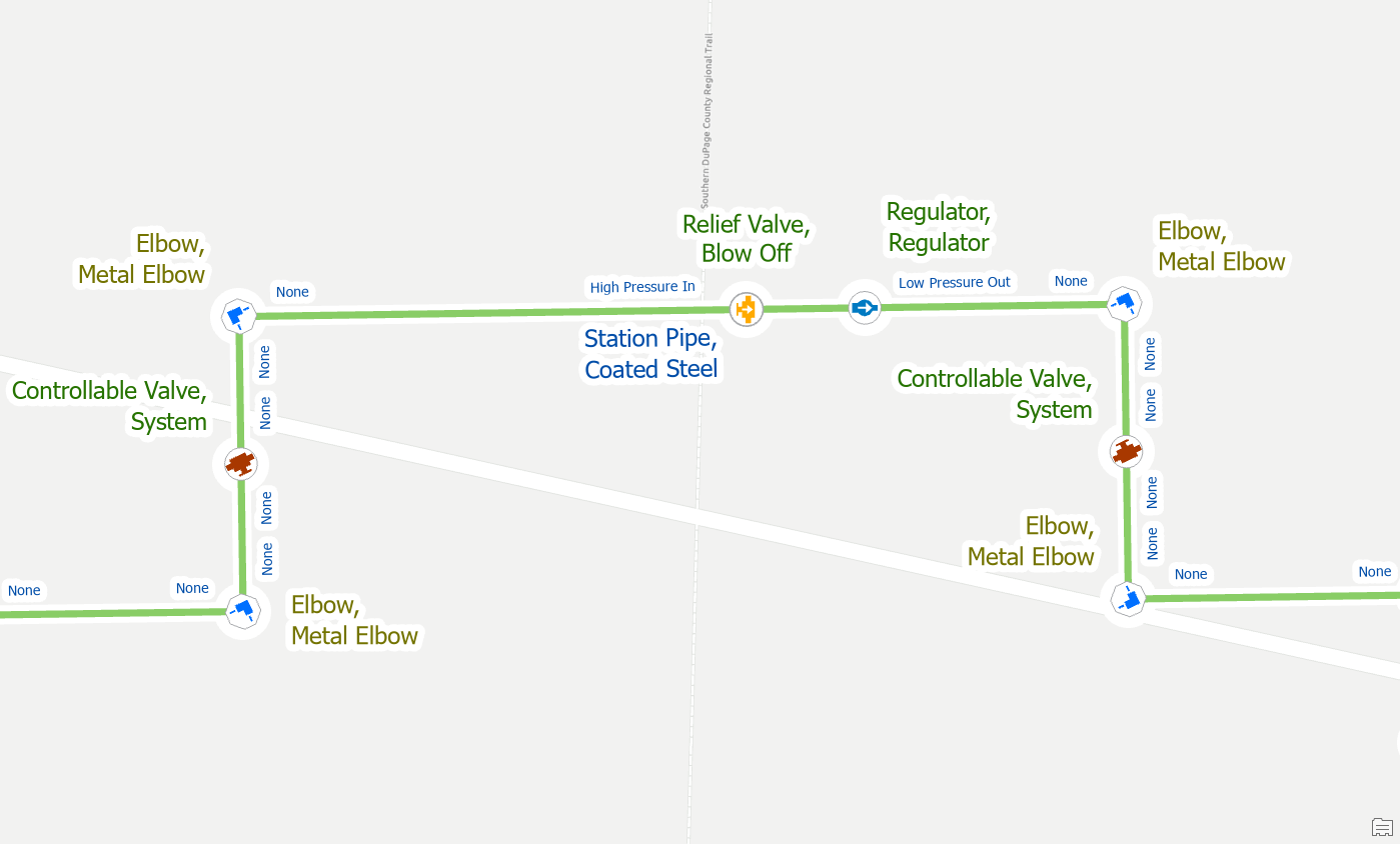
First, we move the regulator to the other side of the blow off valve, if we validate at this point, we will see that we have many errors.
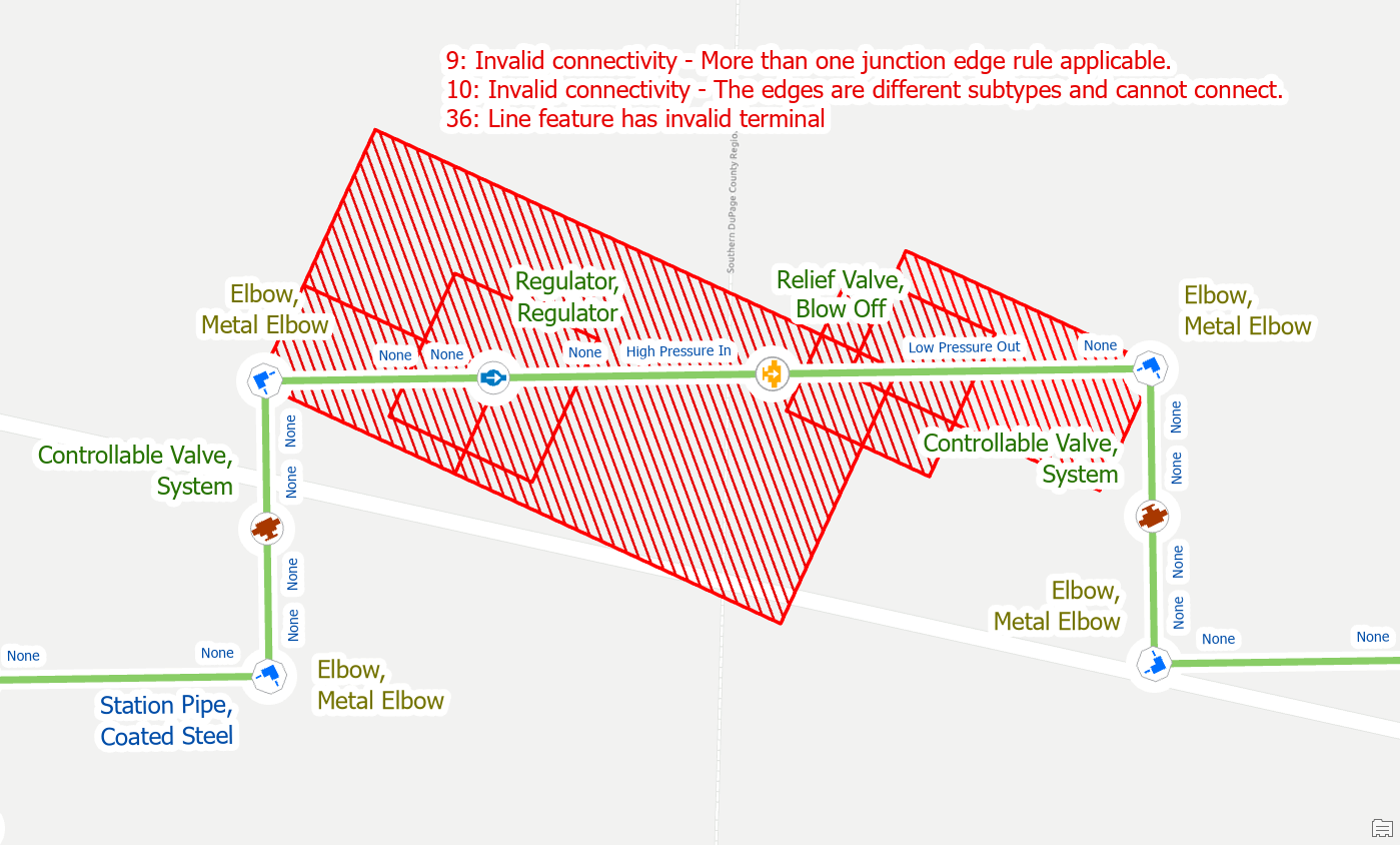
First, use the Modify Terminal Connections pane to remove the invalid terminal connections from the old lines.
Once you’ve reset the terminal connection you can then use the modify terminal connections tool to assign the new terminal.
Finally, you validate your edits to resolve the errors.
Midspan Terminal Device
Split the Line
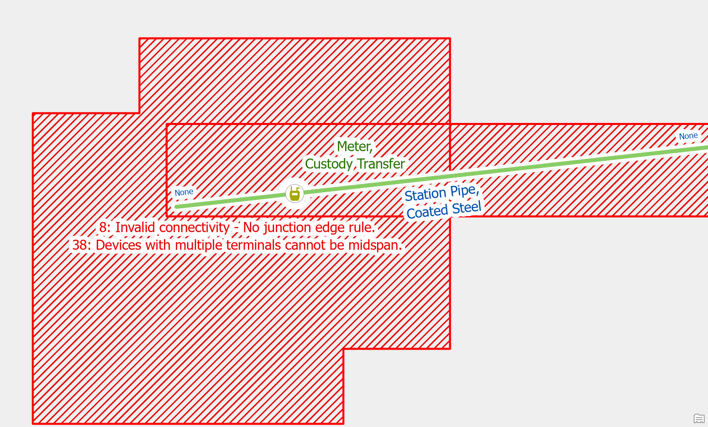
If you place a device with terminals on a line without splitting it first, you will receive this error. Utility Network devices with a terminal configuration are required to be at the end of the pipe or wire. You are likely to receive this error when placing new check valves or pressure reducing valves.
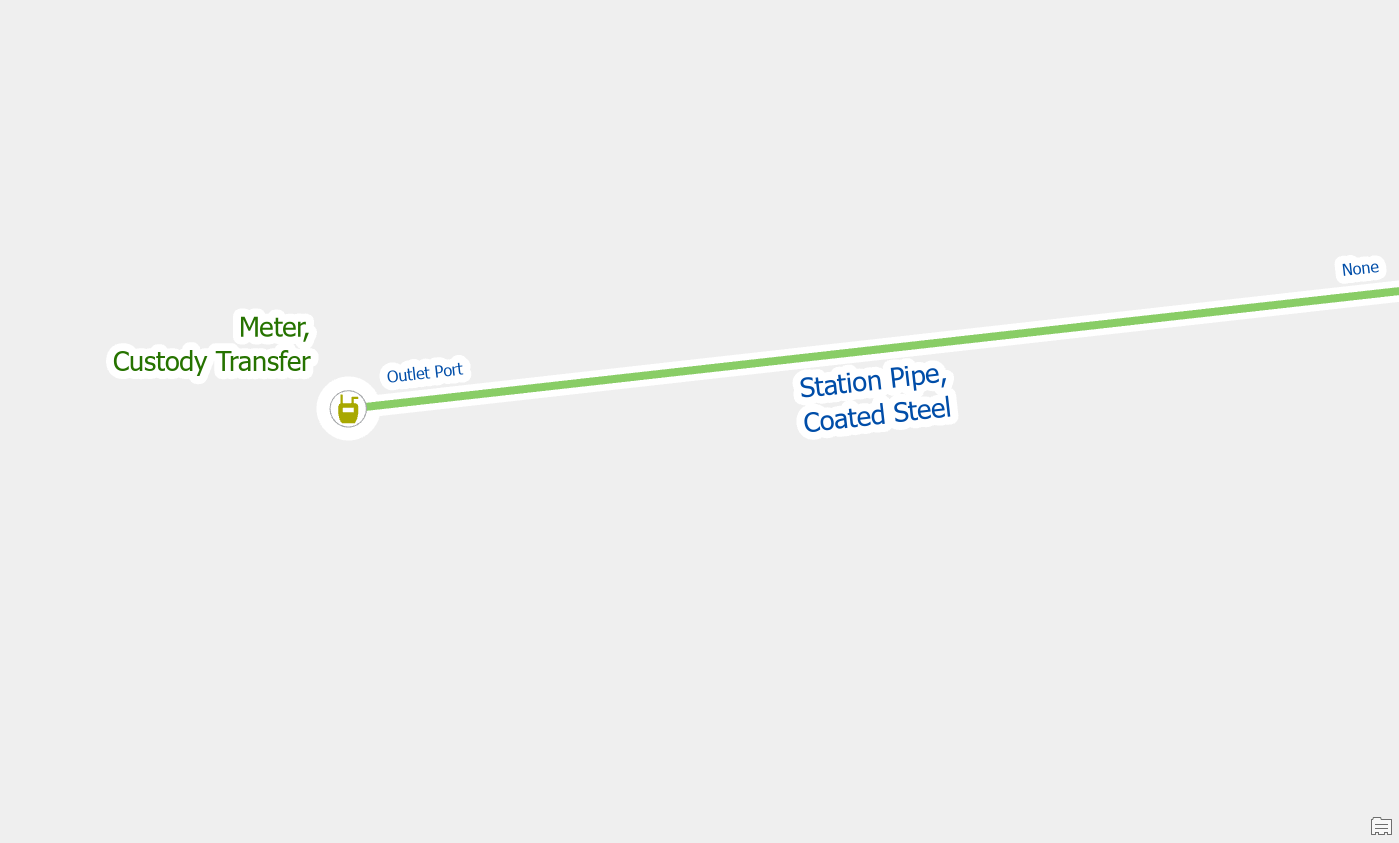
To fix the issue, use the edit tool to split the line at the location where the device connects to the line. After splitting the line, you will still need to use the modify terminal connections tool to connect the lines to the correct terminals on the device.
Once you’ve made and validated the edits in the area, the errors will be resolved.
Move the device
Devices with terminals can only connect to the end of a line.
Before you split the line you should see if the line has already been split in a suitable location for you to connect the device and assign terminals. After you’ve moved the device, you will still need to use the modify terminal connections tool to connect the lines to the correct terminals on the device.
Once you’ve connected the terminals to the device in its new location and validated the area the errors will be resolved.


Commenting is not enabled for this article.