You want to transform your data vertically, but the vertical transformation you need does not exist in ArcGIS Pro. What to do? No problem. ArcGIS Pro 3.2 allows you to create your own custom vertical transformation (CVT) with the new Create Custom Vertical Transformation geoprocessing tool in the Data Management toolbox.
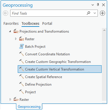
Sometimes you have data in an ArcGIS Pro supported Vertical Coordinate System (VCS) and need to transform them vertically to a user-defined VCS. Or you may need to transform data between two user-defined VCSs. For example, you have a grid of locally derived vertical shifts that you want to apply to your data. Use the Create Custom Vertical Transformation geoprocessing tool in these and other similar cases to solve the problem. Here’s how to do it.
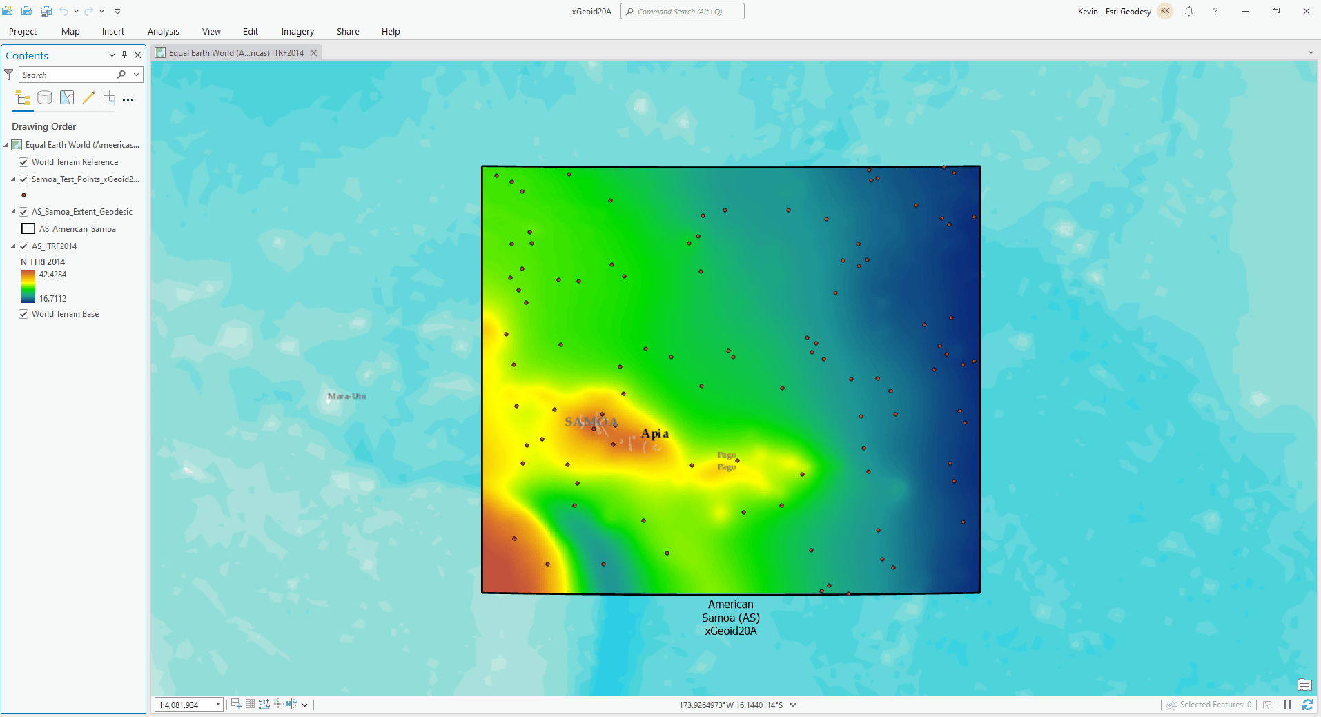
Here we are in ArcGIS Pro (below) with a point feature class overlaid by a raster map of the NOAA National Geodetic Survey xGeoid20A geoid model of American Samoa. A geoid model can be used to transform heights between ellipsoidal and gravity-related height systems. In this case, we want to transform ellipsoidal heights from ITRF2014 to the gravity-based vertical coordinate system (VCS) of American Samoa.
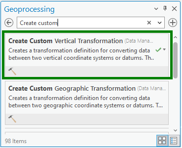
Under Analysis > Tools > Geoprocessing search for and select the Create Custom Vertical Transformation tool.
Enter the parameters of the vertical transformation you require in the tool dialog box. Here is an example:
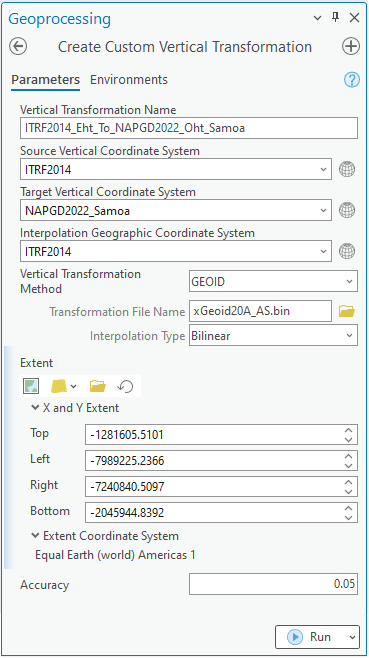
We’ve selected GEOID as our Vertical Transformation Method, which requires you to set a few additional parameters. These are: (1) the Interpolation Geographic Coordinate System, (2) the Transformation File Name (in this case, the xGeoid20A_AS.bin grid file), and (3) the Interpolation Type.
Finally, the tool also collects the Extent information within which the custom vertical transformation is valid and a general statement of transformation accuracy in meters. Both are used to sort the custom transformation in the list of available transformation paths. Click Run and your custom vertical transformation will be saved.
In the example above, we have selected GEOID as the Vertical Transformation Method. Other vertical transformation methods are also available, as shown below.
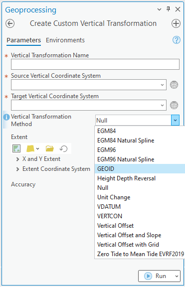
If you select a vertical transformation method that interpolates from a grid, you must store the grid file on disk in the corresponding \pedata folder where you installed the ArcGIS Coordinate Systems Data software component. For instance, for the GEOID method in the example above, the grid file must be stored at:
“…\ArcGIS\CoordinateSystemsData\pedata\vertical\north-america\us\geoid”.
The file extension “.bin” in the Transformation File Name indicates a binary file format. An ASCII geoid grid file may also be used. The file structure of this ASCII file comprises a one-line header followed by the data in row-major format. The one-line header contains four floats (real*8) followed by three long integers (int*4) all space delimited as follows:
SLAT WLON DLAT DLON NLAT NLON IKIND
VALUE VALUE VALUE …
where,
- SLAT: Southernmost latitude in decimal degrees (latitude of lower left corner). Use a minus sign (‒) to indicate South latitudes.
- WLON: Westernmost longitude in decimal degrees (longitude of lower left corner). Use a minus sign (‒) to indicate West longitudes. If the grid crosses the antemeridian (±180 degrees), longitude can be provided in 0-360 degrees range.
- DLAT: Distance interval in latitude in decimal degrees (point spacing in N-S direction).
- DLON: Distance interval in longitude in decimal degrees (point spacing in W-E direction).
- NLAT: Number of rows (starts with SLAT and moves northward DLAT to next row).
- NLON: Number of columns (starts with WLON and moves eastward DLON to next column).
- IKIND: Always equal to 1 (indicates data are doubles (real*4) and endian condition).
The geoid undulation data in meters follows the one-line header. The first row represents the southernmost row of data, with the first data point being in the lower left (SW) corner. This row has NLON values spaced at DLON intervals, and then increments to the next row, which is DLAT to the north. This continues until the last row, where the last value represents the northeast or upper-right (NE) corner. The easternmost longitude is equal to WLON + (NLON – 1) x DLON, while the northernmost latitude is equal to SLAT + (NLAT – 1) x DLAT. The NODATA value is given by 9999. Line breaks and carriage returns are ignored when the tool reads the file. An example of the file is shown below.
-12.0 140.0 0.04166666666666666 0.04166666666666666 289 433 1
63.7249985 63.7700005 63.8219986 63.8829994 63.9529991 64.0260010
64.0889969 64.1399994 64.1829987 64.2210007 64.2559967 64.2860031
64.3170013 64.3519974 64.3899994 9999 9999 9999
. . .
This file format is identical to that used by the U.S. National Geodetic Survey for their geoid files. More information about the format can be found here.
Once you run the Create Custom Vertical Transformation tool, the custom vertical transformation you created becomes available in the Map Properties Transformation drop-down menu. It can then be applied to your map or scene data in ArcGIS Pro as well as with other geoprocessing tools.
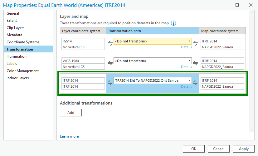
You are now ready to apply your custom vertical transformation to your data using the Project tool. Set the coordinate systems you want for your transformed data by clicking on the Select Coordinate System button (globe icon) next to the Output Coordinate System box and then selecting your desired geographic (GCS) or projected (PCS) and vertical (VCS) coordinate systems in the Coordinate System picker. Click OK.
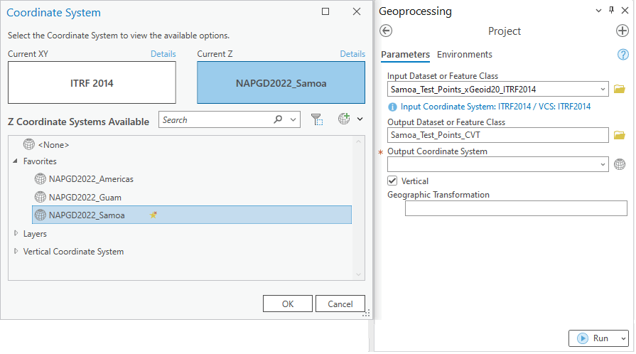
To perform a vertical transformation, make sure the Vertical parameter checkbox is checked. Your custom vertical transformation will show up in the Geographic Transformation drop-down menu. Note that if the selected GCS differs from that of the Input Dataset or Feature Class, a valid transformation path must exist in ArcGIS Pro, otherwise no transformation will be displayed in the Geographic Transformation box.
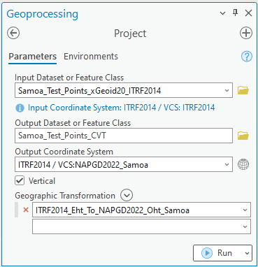
Finally, click Run and you’ve successfully transformed your data using the vertical transformation you defined with the Create Custom Vertical Transformation tool.
Use the ArcGIS Pro Create Custom Vertical Transformation geoprocessing tool when you need to transform data vertically between a Pro supported VCS and a user-defined VCS or between two user-defined VCSs. It’s new at Pro 3.2.
Additional Resources
What You Should Know About Geographic (Datum) and Vertical Transformations
Introducing Coordinate Systems and Transformations
Having a bad case of RTK vertigo?

Commenting is not enabled for this article.