In the last blog, you learned the differences between subnetwork system diagrams and standard diagrams at their creation and update.
In this blog, you will learn about network diagram consistency states and how they switch for subnetwork system diagrams and standard diagrams during your typical daily workflow.
Main network diagram consistency states
Regardless of the type of diagram, the diagram consistency state mainly depends on the following factors:
- Network editing space—Are there dirty areas in the network that impact features of the diagrams?
- Network topology space—Has the network topology been validated since diagram generation or the last update? Did this topology validation concern features or objects that are used in the diagram? Did it impact an extent that intersects the diagram’s geographical extent?
Network diagram inconsistent warning icons regarding the network space
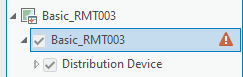
When a diagram is inconsistent, a warning icon appears next to the network diagram layer in the Contents pane. This icon is different depending on the type of diagram inconsistency:
- A red warning icon represents a diagram that is inconsistent with the network editing space.
- An orange warning icon represents a diagram that is inconsistent with the network topology space.
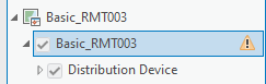
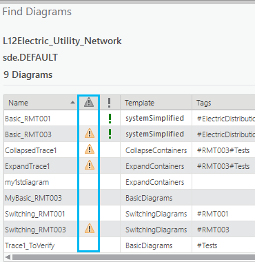
This orange warning icon also appears next to diagram items in the Find Diagrams pane when they are inconsistent with the network topology space.
Consistency state changes on standard and subnetwork system diagrams
Standard and subnetwork system diagram consistency states change during typical workflow such as when editing network features or network objects, when validating network topology on different geographic extent, and when disabling and enabling network topology. The next sections explain how these changes impact the diagram consistency state for each type of diagram.
Diagram consistency state changes when editing the network space
Regardless of whether the diagram is a subnetwork system diagram, the management of its consistency state regarding the network editing space is the same. This means that any diagram becomes inconsistent with the network editing space after any edits on network elements used in it.
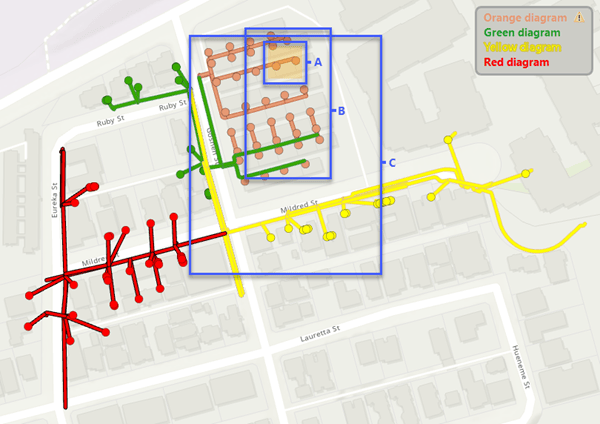
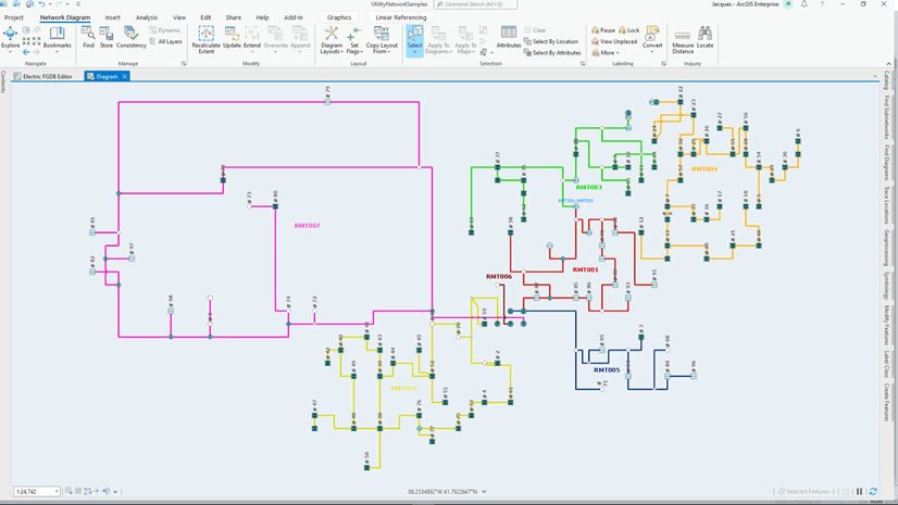
Let’s examine this concept through an example. Below is a sample network map extent. There are four diagrams that partially cover this extent: a green diagram, an orange diagram, a red diagram, and a yellow diagram.
Network features have been edited; they are under the dashed blue dirty area in the network map. Because these edited features are represented in the orange diagram, this makes the orange diagram inconsistent with the network editing space whether it is a standard diagram or a subnetwork system diagram. This is represented by the red icon next to the diagram layer in the Contents pane. The other three diagrams are still consistent.
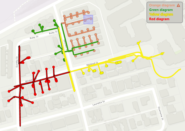
Diagram consistency state changes when editing the network topology space
The consistency state regarding the network topology space is slightly different between a standard diagram and a subnetwork system diagram.
- A standard diagram becomes inconsistent with the network topology space after a topology validation on an extent that intersects the diagram geographic area. This means that a standard diagram becomes inconsistent with the network topology space after topology validation on an extent that includes dirty areas related to network elements used in the diagram. But it can also become inconsistent with the network topology space after validating an extent that partially covers its geographic extent even without any edits on network elements used in it.
As a consequence, the larger the validated geographic extent, the higher the number of standard diagrams covering this extent is likely to be. - Validating network topology on an extent that intersects a subnetwork system diagram’s geographic area doesn’t automatically make it become inconsistent with the network topology space, as it does for a standard diagram. The validation must include edited network elements that are used in the subnetwork system diagram. However, when there is more than one subnetwork controller associated with the edited subnetwork, any associated subnetworks and the related system diagrams also become inconsistent with the network topology space after its validation regardless of the size of the validated geographic extent.
Let’s go back to the network map above and exemplify the differences when validating network topology on various sample extents.
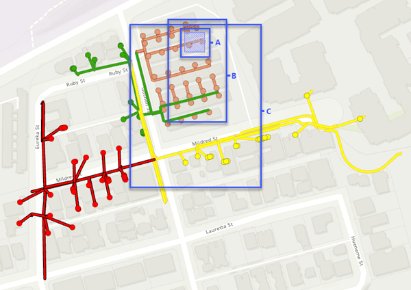
The graphic below shows three geographic extents: A, B, and C. They all include the edited diagram features present under the dashed blue dirty area in the network map.
Standard diagram consistency state change when validating network topology on different extents
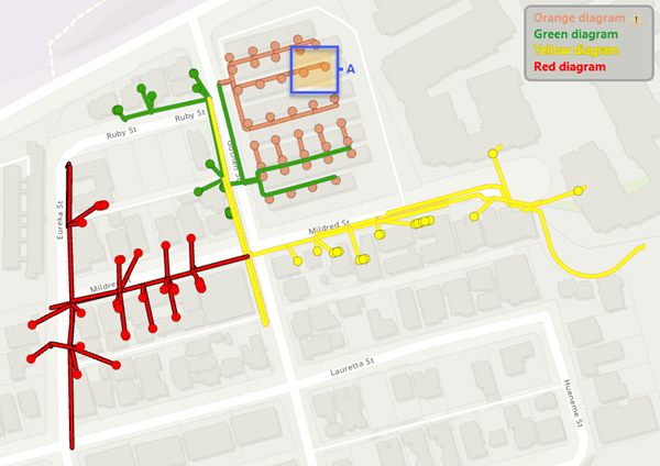
To include these edited feature changes , suppose that a user validates the network topology for extent A below. Once the network topology validation completes, the orange standard diagram whose geographic extent intersects the A extent, becomes inconsistent with the network topology space. This is represented by an orange icon next to the diagram layer in the Contents pane. The other three diagrams are consistent.
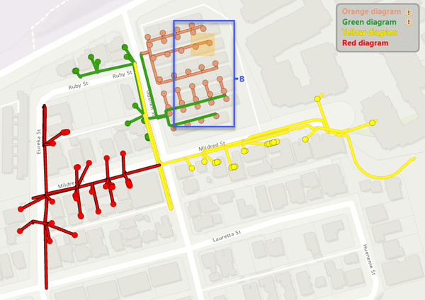
If instead of validating the network topology for extent A, the validation is done for extent B, this causes the orange and green standard diagrams to become inconsistent with the network topology space. The other two diagrams are consistent.
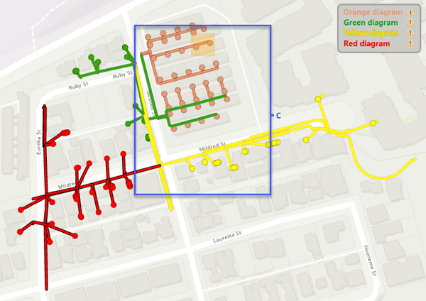
If the network topology validation extent is C, which intersects all of the existing standard diagram geographic extents, the four diagrams become inconsistent with the network topology space.
Subnetwork system diagram consistency state change when validating network topology
Suppose that these four diagrams are subnetwork system diagrams. Regardless of the validated extent—that is, A, B, or C—the orange subnetwork system diagram is the only diagram that becomes inconsistent with the network topology space once the network topology validation completes.
The only exception is if there is more than one subnetwork controller associated with the orange subnetwork. When validating network topology, a post-build trace is run in memory to discover the subnetwork controllers associated with the edits. With a hierarchical tier definition, the trace can retrieve multiple subnetwork controllers. In this case, all the subnetworks related to the retrieved controllers become dirty and the related subnetwork system diagrams become inconsistent with the network topology space.
Diagram consistency state changes when disabling and enabling the network topology
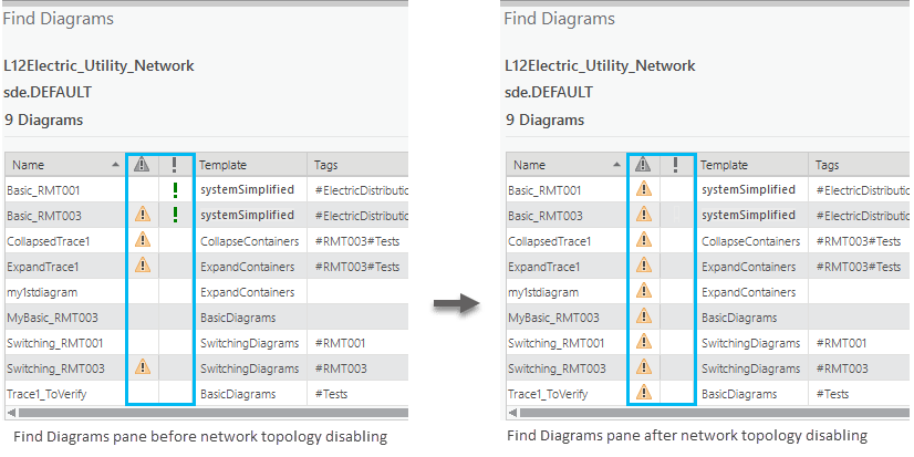
Disabling and enabling the network topology also impacts the consistency state of diagrams. Disabling the network topology causes any diagram to become inconsistent with the network topology space, whether it is a standard or subnetwork system diagram. This is represented by the orange icon in the second column in the Find Diagrams pane.
Moreover, any subnetwork system diagram is no longer considered as system once the network topology is disabled. The green exclamation point in the third column in the Find Diagrams pane disappears for any subnetwork system diagram.
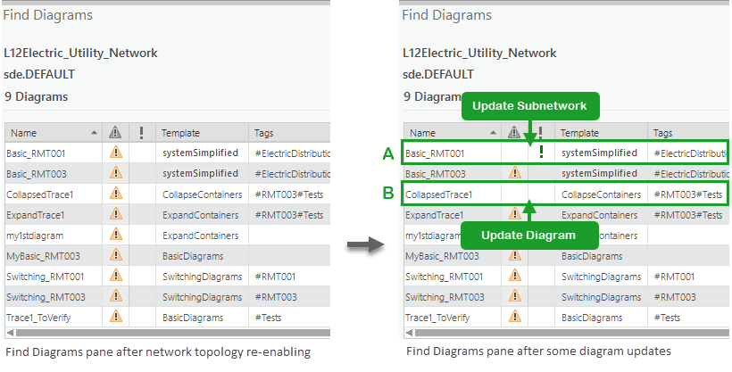
These diagram status and consistency state changes persist once the network topology is re-enabled.
As you run the Update Subnetwork tool on your dirty subnetworks, the subnetwork system diagrams will be rebuilt and they will become consistent subnetwork system diagrams (situation A below).
To make standard diagrams consistent again, run the Update Diagram tool on each inconsistent standard diagram (situation B below).
Summary
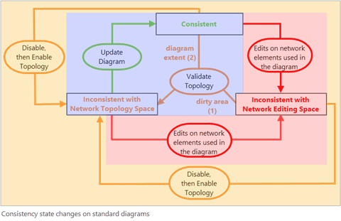
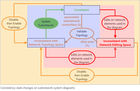
The two graphics below summarize how the consistency state can change during a typical workflow for standard diagrams and subnetwork system diagrams.
- A standard diagram becomes inconsistent with the network editing space following edits that occur on network elements used in it regardless of the consistency state it was in before—the area in red in the graphic below.
Then it becomes inconsistent with the network topology space after topology validation on an extent that includes these newly edited network elements—see (1) in the blue area below.
Even without any edits on network elements used in a standard diagram, it switches from a consistent state to being inconsistent with the network topology space after network topology validation on any extent that intersects its geographic extent—(2) in the blue area below.
To get back to a consistent standard diagram, you must run the Update Diagram tool.
Disabling and re-enabling network topology makes any standard diagrams become inconsistent with network topology space regardless of the consistency state they were in before—the area in orange in the graphic below.
- A consistent subnetwork system diagram becomes inconsistent with the network editing space following edits that occur on network elements used in it regardless of the consistency state it was in before—the area in red in the graphic below.
Then it switches to inconsistent with the network topology space after topology validation on an extent that includes these newly edited network elements—(1) in the blue area below
When there is more than one subnetwork controller associated with the edited subnetwork, any associated subnetwork system diagrams switch from consistent to inconsistent with the network topology space after network topology validation for the edited subnetwork—(3) in the blue area below..
To get back to a consistent subnetwork system diagram, you must run the Update Subnetwork tool.
Disabling and re-enabling network topology makes any subnetwork system diagrams become inconsistent with network topology space regardless of the consistency state they were in before—the area in orange in the graphic below.
Conclusion
This blog explained the main network diagram consistency state switching you may encounter during a typical daily workflow.
Other diagram consistency state switching may happen after diagram template definition changes or due to inconsistent layers, but the management of these changes is the responsibility of the network diagram administrator.
To learn about these other consistency states and for deeper information about network diagram consistency in general—for example, to understand how consistency state is managed in the database, read the Network diagram consistency help topic.
Article Discussion: